 English

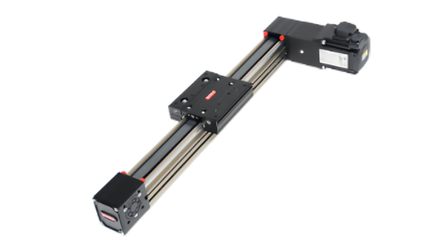
Timing beltlinear modulesare often chosen for long travel and high speed, but engineers frequently ask the same question before using them in positioning equipment: how accurate can a belt-driven axis really be?
The answer depends on what “accuracy” means in the application. A timing belt stage can return to the same taught position very consistently while still having a larger absolute position error over its full stroke. Belt elasticity, tension, pulley geometry, load variation, temperature and feedback method all influence the result.
This guide explainstiming belt linear module accuracyby separating repeatability from positioning accuracy, then shows where belt-driven positioning error comes from and how mechanical design, feedback and compensation can improve performance.
Repeatability and Positioning Accuracy Are Different
Repeatabilitydescribes how closely the carriage returns to the same target position when the same move is repeated.Positioning accuracydescribes how close the actual carriage position is to the commanded coordinate.
| Metric | What It Measures | Typical Use |
|---|---|---|
| Repeatability | Scatter when returning to the same target | Pick and place, assembly, loading and unloading |
| Positioning accuracy | Difference between command and actual position | Coordinate-based positioning, inspection, measurement |
| Reversal error | Difference caused by approaching from opposite directions | Bidirectional positioning |
| Straightness | Deviation of the carriage path from an ideal straight line | Scanning, optical inspection, long-travel guidance |
Important distinction:a belt module can have good repeatability without having the same level of absolute positioning accuracy over the full stroke.
A Simple Example: Good Repeatability, Larger Absolute Error
Suppose the controller commands the carriage to move to 1000.00 mm. After repeated moves, the stage stops at approximately 1000.12 mm every time.
The repeatability may be very good because the final position changes very little between cycles. But the axis still has an absolute position offset of about 0.12 mm relative to the command.
For a pick-and-place station, that offset may be corrected during teaching and never create a problem. For a measurement system that relies on absolute coordinates, it may be unacceptable.
Why Timing Belt Modules Can Repeat Well
A toothed timing belt provides positive engagement with the pulley. Unlike a friction belt, it does not depend on continuous slip to transmit motion.
If the belt tension, pulley engagement, load and mechanical structure remain stable, the system can return to the same pulley tooth relationship repeatedly.
Good repeatability is supported by:
- Stable belt tension
- Correct pulley alignment
- A rigid carriage and guide structure
- Low variation in load
- Consistent approach direction
- Proper servo or stepper sizing
- Stable mechanical temperature
Where Timing Belt Positioning Error Comes From
A belt-driven stage has an error chain that extends from the motor command to the actual carriage position.
| Error Source | Possible Effect | Typical Control Method |
|---|---|---|
| Belt elastic stretch | Load-dependent position shift | Higher belt stiffness, lower force, feedback |
| Belt pitch variation | Position-dependent error over travel | Quality belt, calibration |
| Pulley pitch diameter error | Scale error between motor rotation and travel | Precision pulley, calibration |
| Pulley eccentricity or runout | Periodic position variation | Better pulley and shaft alignment |
| Insufficient belt tension | Reversal error, vibration, poor repeatability | Correct tension setting |
| Structural deflection | Tool position changes under load | Higher stiffness, reduced overhang |
| Guide straightness | Lateral or vertical path error | Precision guide and installation |
| Thermal effects | Position drift over time | Temperature stabilization and compensation |
| Control following error | Dynamic position differs from command | Motor sizing and servo tuning |
Belt Elongation Is Not the Same as Permanent Stretch
The phrase “belt stretch” can describe two different effects.
Elastic elongation
When the belt is loaded, it elongates elastically according to its tensile stiffness. If the load is removed and the belt remains within its normal operating range, much of this deformation is recoverable.
This elastic behavior can create a temporary position shift that changes with force and acceleration.
Permanent elongation or damage
Overload, fatigue, material degradation or tensile-member damage can produce a permanent change in belt length or tension. This is a maintenance issue rather than ordinary elastic behavior.
Accuracy implication:a belt may have stable mechanical condition but still deflect elastically under changing load. Absolute positioning should therefore be evaluated at realistic load and acceleration.
How Belt Stiffness Affects Position
The simplest conceptual relationship is:
Elastic displacement ≈ applied force ÷ effective belt stiffness
The exact value depends on belt construction, tensile members, belt width, free belt length, tension and geometry.
This means position shift tends to increase when:
- Drive force increases
- The belt span becomes longer
- The belt is narrower or less stiff
- Acceleration increases
- The moving load increases
This is one reason long-stroke belt stages should not be evaluated from repeatability alone if the application needs tight absolute positioning under variable load.
Why Load Direction Matters
A belt axis may behave differently depending on whether the carriage is being pulled from one side of the belt or the other.
When the direction reverses, the tension distribution in the belt changes. If the system has insufficient pretension, structural compliance or pulley play, the final position can shift.
Unidirectional approach can improve consistency
If the process allows it, critical positions can be approached from the same direction every cycle. This keeps belt loading and mechanical preload more consistent.
This strategy does not improve the fundamental absolute scale accuracy, but it can reduce reversal-related variation in applications where bidirectional positioning is not required.
Belt Tension Has a Direct Effect on Repeatability
Correct pretension helps maintain tooth engagement and reduces unwanted free movement in the drive system.
If tension is too low
Possible effects include:
- Higher reversal error
- Belt vibration
- Tooth jump under aggressive acceleration
- Reduced positioning consistency
If tension is too high
Excessive tension can:
- Increase pulley bearing load
- Increase motor torque demand
- Accelerate belt fatigue
- Increase structural load
The most accurate setting is not the highest tension. Use the tension specified for the actual module and belt.
Pulley Geometry Converts Motor Rotation Into Linear Distance
The controller usually assumes that a specific motor rotation corresponds to a specific linear movement based on pulley pitch circumference and any gearbox ratio.
If the effective pulley pitch diameter differs from the nominal value, the linear distance per motor revolution will also differ.
Scale error
A small conversion error can become more visible over a long travel. For example, an error of only a fraction of a percent in the rotation-to-distance relationship can accumulate into a much larger absolute position error over a meter-scale stroke.
Periodic error from eccentricity
If the pulley or shaft has measurable eccentricity, the effective belt travel per angular increment can vary through one revolution, creating a repeating position pattern.
Long Stroke Magnifies Some Accuracy Problems
Timing belt modules are attractive because they can achieve long travel without a long rotating screw. However, long travel also means more belt length is involved in the mechanical system.
Longer axes may be more sensitive to:
- Elastic belt displacement
- Thermal length change
- Profile deflection
- Support spacing
- Scale error
- Cable-carrier drag variation
A positioning specification measured over a short section should not automatically be assumed to represent the complete long-stroke axis.
Timing Belt Accuracy Under Acceleration
Static positioning and dynamic positioning are not always identical.
During acceleration, belt force increases because the motor must accelerate the moving mass. The belt and supporting structure therefore deflect more than they do at rest.
The axis can appear accurate after a long settling period but still have significant dynamic following error during a fast move.
This matters in applications such as:
- Continuous dispensing
- Line-scan inspection
- High-speed synchronized handling
- Electronic camming
Servo Feedback Improves Control, but Where Is the Encoder?
Many belt-driven axes use a servo motor with an encoder mounted on the motor.
Motor-side feedback tells the controller the motor shaft position. It is excellent for controlling the motor, but the controller still calculates carriage position through the belt and pulley relationship.
Mechanical effects between the motor and carriage—such as belt elasticity, pulley error or structural deflection—are not measured directly by a motor encoder.
Closed loop does not automatically mean closed loop at the carriage.The location of the feedback device determines which errors the controller can observe.
What a Linear Encoder Changes
A linear encoder or scale mounted along the axis measures carriage position more directly.
This can allow the control system to observe and compensate for some errors that occur after the motor, including:
- Belt elastic displacement
- Pulley scale error
- Gearbox error
- Some transmission compliance
A direct linear feedback system can significantly improve absolute positioning performance when properly designed.
But a linear scale does not solve every error
It cannot automatically remove:
- Tooling deflection after the carriage
- Poor guide straightness
- Loose fixtures
- Unstable temperature
- Mechanical resonance
The complete machine error chain still needs to be controlled.
Closed-Loop Belt Modules: What Does “Closed Loop” Really Mean?
There are several possible architectures:
| Feedback Architecture | What Is Measured | Main Limitation |
|---|---|---|
| Stepper without encoder | Commanded steps only | No direct confirmation of motor position |
| Closed-loop stepper | Motor position | Transmission error remains outside the motor feedback loop |
| Servo with motor encoder | Motor position and speed | Belt and carriage error are inferred mechanically |
| Servo with linear encoder | Carriage position directly | Requires more complex feedback integration |
The term “closed-loop belt module” is therefore incomplete unless the feedback location is specified.
Can Calibration Improve Belt Module Positioning Accuracy?
Yes—if the error is stable and repeatable.
Calibration measures the difference between commanded and actual position along the stroke. If the error follows a consistent pattern, the controller can use a compensation table.
Errors that may respond well to compensation
- Stable pulley scale error
- Repeatable pitch-related error
- Repeatable position-dependent mechanical error
Errors that are difficult to compensate
- Load-dependent belt deflection that changes every cycle
- Changing belt tension
- Loose pulleys or fasteners
- Random contamination
- Thermal conditions that vary unpredictably
Compensation works best when the mechanical system is already stable.
Temperature Affects More Than the Belt
Temperature changes can alter the belt, aluminum module body, pulley spacing, guide system and machine frame.
Possible heat sources include:
- Motor losses
- High cycle rate
- Pulley bearings
- Nearby process equipment
- Ambient temperature changes
For ordinary pick-and-place equipment, the resulting drift may be acceptable. For long-stroke inspection or calibrated positioning, thermal stability may become part of the error budget.
Guide Accuracy Still Matters on a Belt Stage
The belt determines motion along the drive direction, but the guide determines the carriage path.
Even if X-axis positioning is repeatable, poor guide straightness can cause Y or Z deviation during travel.
For applications such as camera scanning, dispensing or optical alignment, specify:
- Horizontal straightness
- Vertical straightness
- Pitch
- Yaw
- Roll if relevant
Structural Stiffness Can Dominate Tool-Point Accuracy
A timing belt carriage may stop correctly while the actual tool continues to move because the mounting bracket or machine frame deflects.
This is common with:
- Long gripper arms
- Large camera brackets
- Wide fixtures
- Multi-axis gantry crossbeams
Tool-center accuracy should therefore be evaluated from:
Motor → pulley → belt → carriage → mounting structure → tool
How to Improve Timing Belt Module Accuracy
1. Define the correct accuracy metric
Specify repeatability, absolute positioning accuracy, reversal error, straightness and settling separately.
2. Use a suitably stiff belt
Higher tensile stiffness and appropriate belt width can reduce load-dependent elastic displacement.
3. Set belt tension correctly
Maintain the manufacturer's specified tension. Too loose and too tight can both reduce performance.
4. Reduce unnecessary peak force
Lower acceleration or smoother motion profiles can reduce elastic belt deflection and structural vibration.
5. Improve pulley and shaft quality
Precision pitch geometry, low runout and correct alignment reduce periodic and scale errors.
6. Increase structural stiffness
Reduce tooling overhang and improve frame support so carriage accuracy reaches the actual process point.
7. Use consistent approach direction where practical
This can reduce reversal-related variation in taught-position applications.
8. Add direct linear feedback when absolute accuracy justifies it
A linear scale allows the controller to measure carriage position rather than infer it only from motor rotation.
9. Calibrate the assembled axis
Calibration after installation captures the effect of pulley scale, machine structure and mounting conditions more effectively than component-level data alone.
When Is a Timing Belt Module Accurate Enough?
The answer depends on the process.
| Application | Primary Accuracy Concern |
|---|---|
| General transfer | Reliable endpoint repeatability |
| Pick and place | Repeatability and settling |
| Dispensing | Path repeatability and speed stability |
| Vision inspection | Repeatability, straightness and possibly absolute accuracy |
| Calibrated measurement | Absolute accuracy and thermal stability |
A belt stage that is ideal for high-speed handling may not be the right choice for a metrology axis, and that does not make the belt stage a poor design. It means the drive should be matched to the process requirement.
What to Ask a Supplier About Belt Module Accuracy
- Is the stated value repeatability or positioning accuracy?
- Is it measured over the full stroke?
- Is the test single-direction or bidirectional?
- What payload is used during the test?
- What belt tension is specified?
- Does the value include reversal error?
- What feedback system is used?
- Is the feedback located on the motor or carriage?
- Are straightness and angular errors specified separately?
- Can the assembled axis be calibrated?
What QRXQ Needs to Evaluate a Belt-Driven Precision Application
- Required stroke
- Moving mass
- Center-of-gravity position
- Maximum speed and acceleration
- Repeatability requirement
- Absolute positioning requirement if applicable
- Bidirectional or unidirectional positioning
- Horizontal, vertical or gantry installation
- Motor and feedback preference
- Temperature range
- Cycle rate
- Tooling structure
The practical question is not “Are timing belt modules precise?”It is “Which accuracy metric does this process need, and which part of the belt-drive error chain must be controlled to achieve it?”
QRXQ evaluatestiming belt linear moduleaccuracy from repeatability, load-dependent belt deflection, pulley geometry, feedback architecture and machine structure together rather than relying on one catalog tolerance.
