 English

Atiming belt linear moduleis widely used in industrial automation applications that require high travel speed, long stroke, rapid acceleration and frequent reciprocating movement. However, engineers evaluating this type of actuator often ask an important question:how accurate is a timing belt linear module?
The answer depends on how accuracy is defined. Positioning accuracy, repeatability, resolution and motion stability are related performance indicators, but they do not describe exactly the same characteristic. A timing belt linear module may return to the same position consistently while still having a measurable absolute positioning error across its full travel.
The final positioning performance is influenced by belt elasticity, transmission backlash, pulley machining accuracy, guide rail precision, servo tuning, encoder feedback, installation quality, payload, acceleration and operating temperature. Understanding these factors helps engineers determine whether a belt-driven linear axis is suitable for a specific automation process and how its precision can be improved.
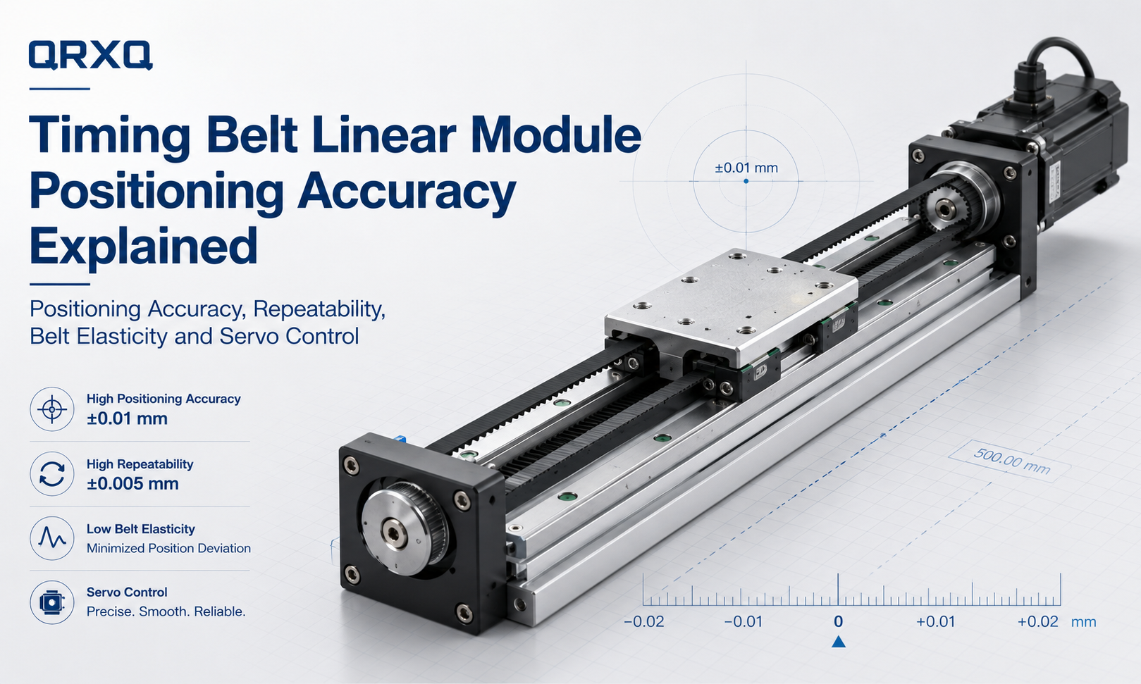
What Is Timing Belt Linear Module Positioning Accuracy?
Positioning accuracydescribes how closely the actual position of the carriage matches the commanded position. For example, if the controller commands the carriage to move to 500.00 mm but the measured position is 500.12 mm, the positioning error is 0.12 mm.
Positioning accuracy is normally evaluated across multiple points throughout the effective stroke. The actual carriage position is measured using an external measuring instrument and compared with the position commanded by themotion controller.
The difference between the commanded value and the measured value may be caused by several factors, including:
- Timing belt elongation under load
- Dimensional variation in the timing belt tooth pitch
- Pulley pitch diameter errors
- Transmission clearance or mechanical backlash
- Guide rail straightness and installation errors
- Motor and encoder resolution
- Servo following error
- Structural deformation
- Temperature-related expansion
Because these errors may accumulate over a long travel distance, the absolute positioning accuracy of a timing belt actuator is often related to its stroke length.
Positioning Accuracy vs Repeatability
Positioning accuracy and repeatability are frequently confused, but they measure different aspects of motion performance.
Positioning Accuracy
Positioning accuracy indicates whether the carriage reaches the exact commanded coordinate. It evaluates the difference between the target position and the actual measured position.
A module can repeatedly stop at 500.10 mm when commanded to move to 500.00 mm. In this case, the movement is consistent, but an absolute positioning deviation of 0.10 mm remains.
Repeatability
Repeatabilitydescribes the ability of the module to return to the same position after multiple repeated movements under the same operating conditions.
If the carriage repeatedly stops between 500.08 mm and 500.12 mm, the repeatability variation is relatively small even though the average position differs from the commanded coordinate.
Why the Difference Matters
Repeatability is often more important than absolute positioning accuracy in applications such as:
- Pick-and-place operations
- Material transfer
- Packaging equipment
- Sorting systems
- Loading and unloading mechanisms
- Repeated dispensing operations
Absolute positioning accuracy becomes more important when the system must move to many different coordinates without relying on local calibration, mechanical stops or vision correction.
| Performance Indicator | What It Measures | Typical Concern |
|---|---|---|
| Positioning Accuracy | Difference between commanded and actual position | Absolute coordinate error |
| Repeatability | Variation when returning to the same position repeatedly | Consistency of repeated movement |
| Resolution | Smallest movement command the control system can generate | Minimum controllable increment |
| Backlash | Lost motion when the travel direction changes | Bidirectional positioning error |
| Straightness | Deviation from an ideal straight travel path | Lateral or vertical motion error |
How Accurate Is a Timing Belt Linear Module?
The accuracy of a timing belt linear module depends on its structural design, belt type, pulley quality, guide system, control method, stroke and operating conditions. There is no single accuracy value that applies to every belt-driven actuator.
In general, timing belt modules are designed primarily for high speed, long stroke and efficient material movement rather than ultra-high-precision machining. Many industrial models provide repeatability in the range of several hundredths of a millimetre, while absolute positioning error may be larger and may increase over longer travel distances.
These values should only be treated as general references. Actual performance must be confirmed using the manufacturer’s technical specifications, stated test conditions and the effective stroke required by the application.
Higher-precision belt modules can achieve better results by using:
- Steel-cord or aramid-cord reinforced timing belts
- Precision-machined pulleys
- Optimized belt pretension
- High-rigidity linear guides
- Servo motors with high-resolution encoders
- Closed-loop position feedback
- Laser calibration and controller compensation
Main Factors Affecting Timing Belt Module Accuracy
1. Timing Belt Elasticity
The timing belt is a flexible transmission component. When the carriage accelerates, decelerates or carries an external load, tensile force acts on the belt. This force can produce temporary elastic elongation.
The amount of elongation depends on:
- Belt material
- Tension-member construction
- Belt width
- Effective belt length
- Applied load
- Acceleration
- Belt pretension
A longer belt generally has more potential elastic deformation than a shorter belt under the same tensile force. This is one reason why long-stroke timing belt modules may have greater absolute positioning deviation.
Elastic deformation is not always a permanent error. After the load is removed, the belt may return close to its original length. However, during dynamic movement, this elasticity can cause following error, settling time and position deviation.
2. Belt Tooth Pitch Accuracy
A timing belt contains a series of equally spaced teeth that engage with the pulley. Small manufacturing variations in tooth pitch can influence the relationship between pulley rotation and actual linear travel.
When the axis moves over a long distance, small pitch deviations may accumulate. High-quality belts with stable tooth geometry and reinforced tension members generally provide more predictable movement than low-quality belts.
The belt should also match the pulley tooth profile. An incorrect belt and pulley combination can cause poor engagement, uneven motion, accelerated wear and reduced positioning stability.
3. Belt Pretension
Correct belt tension is essential for accurate motion transmission.
If the belt tension is too low, the system may experience:
- Tooth jumping
- Belt vibration
- Delayed response
- Direction-change error
- Unstable positioning
- Abnormal noise
If the belt tension is too high, it may increase:
- Pulley bearing load
- Motor resistance
- Belt fatigue
- Shaft deformation
- Guide system stress
- Premature component wear
The belt should be tensioned according to the module design and the manufacturer’s recommended adjustment procedure. Increasing tension beyond the specified range does not automatically improve accuracy.
4. Pulley Machining Precision
The drive pulley converts motor rotation into linear belt movement. Errors in pulley diameter, tooth profile, concentricity or shaft installation can directly affect linear displacement.
If the pulley is not concentric with the motor shaft, the effective transmission radius changes slightly during each revolution. This may produce periodic speed fluctuations and cyclic positioning errors.
Pulley-related accuracy depends on:
- Pitch diameter tolerance
- Tooth profile accuracy
- Radial runout
- Axial runout
- Shaft concentricity
- Bearing support rigidity
- Pulley mounting method
Precision-machined pulleys and rigid shaft connections help improve the consistency between motor rotation and carriage displacement.
5. Transmission Backlash
A timing belt drive normally has less mechanical backlash than many conventional gear transmission systems because the belt teeth engage directly with the pulley grooves. However, the system is not completely free from lost motion.
Possible sources of bidirectional positioning error include:
- Clearance between belt teeth and pulley grooves
- Insufficient belt tension
- Belt tooth deformation
- Pulley shaft movement
- Bearing clearance
- Coupling deformation
- Motor shaft torsion
Backlash is particularly noticeable when the carriage reverses direction. For this reason, accuracy tests should include both unidirectional and bidirectional positioning measurements.
6. Linear Guide Accuracy
The timing belt controls movement along the axis, while the linear guide supports the carriage and constrains its travel path. Guide rail quality therefore has a direct influence on motion precision.
Important guide-related factors include:
- Rail straightness
- Mounting surface flatness
- Guide parallelism
- Slider preload
- Running clearance
- Lubrication condition
- Carriage rigidity
If the guide rail is installed on an uneven or twisted mounting surface, the carriage may experience uneven resistance. This can increase servo following error and cause different positioning results at different points along the stroke.
Guide errors can also produce vertical, lateral, pitch, yaw and roll deviations even when the linear coordinate appears correct.
7. Servo Motor and Encoder Resolution
The motor and encoder determine how precisely rotational movement can be controlled and measured.
A higher-resolution encoder allows the controller to detect smaller changes in motor position. However, encoder resolution alone does not determine the final linear accuracy of the module.
The theoretical linear movement per encoder count can be estimated using:
Linear movement per count = Pulley travel per revolution ÷ Encoder counts per revolution
For example, if one pulley revolution produces 100 mm of linear travel and the control system has 1,000,000 effective counts per revolution, the theoretical command increment is 0.0001 mm per count.
This does not mean the module can physically position with an accuracy of 0.0001 mm. Belt elasticity, pulley error, guide accuracy, vibration, structural deformation and controller performance will produce much larger real-world deviations.
8. Servo Tuning and Following Error
The servo drive compares the commanded position with encoder feedback and continuously adjusts motor torque to reduce the difference. The remaining difference during motion is known as following error.
Poor servo tuning may cause:
- Overshoot
- Oscillation
- Long settling time
- Position hunting
- Excessive vibration
- Motor alarms
Servo parameters must be matched to the moving mass, belt stiffness, pulley inertia, acceleration and mechanical rigidity of the system.
A very aggressive gain setting may reduce response delay but increase vibration. A conservative setting may provide smoother motion but require more time to settle at the target position.
9. Payload and Load Distribution
The specified payload of a linear module does not only refer to the total mass placed on the carriage. Load position and moment load also affect motion accuracy.
An off-centre load creates additional pitch, yaw or roll moments on the carriage and guide blocks. Excessive moment load can cause:
- Carriage deflection
- Guide deformation
- Uneven slider resistance
- Increased vibration
- Reduced repeatability
- Accelerated guide wear
The centre of gravity should be positioned as close as practical to the carriage centre and guide plane. Large overhanging loads may require a wider module, dual-guide structure or external support.
10. Speed and Acceleration
High speed does not automatically reduce positioning accuracy, but higher acceleration increases dynamic belt tension, inertial force and structural vibration.
If the acceleration is too high for the selected module, the axis may experience:
- Belt stretching
- Servo lag
- Carriage vibration
- Longer settling time
- Position overshoot
- Tooth jumping under severe conditions
For precision-sensitive operations, the motion profile should include suitable acceleration, deceleration and jerk settings. An S-curve profile can reduce mechanical shock and improve settling stability compared with an abrupt trapezoidal profile.
11. Stroke Length
Timing belt modules are particularly suitable for long-stroke motion, but increasing the stroke also increases the total belt length.
A longer belt may introduce:
- Greater elastic elongation
- More sensitivity to temperature
- More belt vibration
- Higher cumulative pitch deviation
- Lower structural natural frequency
When evaluating a long axis, engineers should not rely only on a repeatability value measured over a short section. Accuracy should be assessed across the full effective travel.
12. Temperature and Environmental Conditions
Temperature changes affect the dimensions and mechanical properties of the belt, aluminium profile, guide rail and mounting structure.
Potential environmental influences include:
- Ambient temperature variation
- Heat generated by the motor
- Direct sunlight
- Nearby heating equipment
- Dust and contamination
- Humidity
- Lubricant viscosity changes
For precision-sensitive equipment, the module should be allowed to reach a stable operating temperature before calibration or measurement.
Unidirectional and Bidirectional Positioning Accuracy
Positioning tests can be performed using unidirectional or bidirectional movement.
Unidirectional Positioning
In a unidirectional test, the carriage approaches each measurement point from the same direction. This method reduces the influence of direction-change clearance and belt tooth deformation.
Unidirectional positioning often produces better results because the belt remains loaded in a consistent direction.
Bidirectional Positioning
In a bidirectional test, the carriage approaches the same position from both directions. This method reveals reversal error, transmission clearance and differences in belt loading.
Applications that frequently reverse direction should be evaluated using bidirectional data rather than unidirectional performance alone.
How Timing Belt Module Accuracy Is Measured
Professional positioning tests normally use an external measuring instrument rather than relying only on motor encoder feedback.
Common measurement equipment includes:
- Laser interferometers
- Linear encoders
- Digital indicators
- Optical measurement systems
- High-precision displacement sensors
A typical positioning accuracy test includes the following steps:
- Install the module on a rigid and level mounting surface.
- Allow the mechanical and electrical system to reach a stable temperature.
- Apply the specified payload and operating conditions.
- Set multiple measurement points across the usable stroke.
- Move the carriage to each target position.
- Measure the actual position using an external reference device.
- Repeat the movement several times.
- Approach the positions from one or both directions.
- Calculate positioning error, repeatability and reversal error.
Test results are only meaningful when the measurement conditions are clearly defined. Payload, speed, acceleration, travel direction, temperature and settling time should all be recorded.
Open-Loop vs Closed-Loop Position Control
Motor-Side Closed Loop
Most servo-driven timing belt modules use an encoder mounted on the motor. The encoder confirms the motor shaft position, but it does not directly measure the actual carriage position.
This configuration can detect motor movement accurately, but mechanical errors occurring after the motor shaft may remain unmeasured. These errors include belt elongation, pulley deformation, coupling movement and frame deflection.
Full Closed-Loop Control
A full closed-loop system uses an external linear encoder installed along the module stroke. The controller receives feedback from the actual carriage position rather than estimating linear travel only from motor rotation.
Full closed-loop feedback can help compensate for:
- Belt elasticity
- Pulley transmission error
- Coupling deformation
- Mechanical backlash
- Temperature-related dimensional changes
However, installing a linear encoder increases system cost, wiring complexity, commissioning requirements and environmental protection needs.
How to Improve Timing Belt Linear Module Precision
Select a High-Quality Reinforced Belt
Choose a timing belt with stable tooth geometry and a low-elongation tensile member. Steel-cord and aramid-cord reinforced belts are commonly used where improved stiffness and dimensional stability are required.
Use the Correct Belt Width
A wider belt generally provides higher tensile stiffness and load capacity. However, the belt width must match the pulley design, module size, motor torque and required acceleration.
Adjust Belt Tension Correctly
Follow the specified tensioning method instead of adjusting the belt only by feel. Recheck the tension after the initial running-in period because the belt and mechanical connections may settle.
Reduce the Moving Mass
Lower moving mass reduces inertial force, dynamic belt elongation and servo load. Fixtures, cables and workpieces mounted on the carriage should be designed as light and rigid as practical.
Control the Load Centre of Gravity
Position the payload close to the carriage centre and minimise overhang. External guide support may be required for wide, tall or eccentric loads.
Optimize the Motion Profile
Use suitable acceleration, deceleration and jerk settings. Avoid unnecessarily aggressive motion commands when the process requires short settling times and stable final positioning.
Improve Mounting Surface Accuracy
The installation base should be rigid, flat and free from distortion. Tightening bolts should be applied in a controlled sequence to prevent twisting the module profile.
Align Multi-Axis Systems Carefully
In XY, XZ, XYZ and gantry systems, poor alignment between axes can generate additional resistance and structural deformation. Parallel axes must be aligned carefully, particularly in dual-drive gantry configurations.
Use Position Compensation
Systematic positioning errors can be measured and stored in the motion controller as a compensation table. The controller then modifies the command value at different locations along the stroke.
Error compensation is effective for repeatable geometric errors, but it cannot fully correct random vibration, unstable belt tension, variable payload deformation or severe mechanical wear.
Add External Position Feedback
For demanding applications, a linear encoder can be installed to measure the actual carriage position. This provides better control of mechanical transmission errors than motor-side feedback alone.
Perform Regular Maintenance
Accuracy may decrease gradually due to belt wear, pulley wear, loose fasteners, guide contamination or insufficient lubrication. Preventive inspection helps maintain stable performance over the module’s service life.
When Is Timing Belt Module Accuracy Sufficient?
A timing belt linear module is generally suitable when the application prioritizes:
- High travel speed
- Long stroke
- Rapid reciprocating movement
- Moderate positioning precision
- High cycle efficiency
- Low moving mass
- Cost-effective multi-axis integration
Typical applications include:
- Packaging machines
- Sorting equipment
- Material handling systems
- Pick-and-place units
- Vision inspection positioning
- Printing equipment
- Automatic loading systems
- Electronics assembly
- Logistics automation
- Dispensing and spraying equipment
In many of these applications, the axis repeatedly moves between taught positions. Stable repeatability may therefore be more important than extremely small absolute coordinate error.
When Should Another Drive Type Be Considered?
Atiming belt modulemay not be the best option when the application requires:
- Micrometre-level absolute positioning
- Very high axial rigidity
- Heavy machining forces
- Extremely low settling error
- High-precision interpolation
- Very small controlled feed increments under load
Depending on the required stroke, speed, load and precision, alternatives may include:
- Ball screw linear modules
- Linear motor stages
- Precision electric cylinders
- Rack-and-pinion axes with external feedback
| Drive Type | Main Strength | General Accuracy Characteristic | Typical Application |
|---|---|---|---|
| Timing Belt | High speed and long stroke | Good repeatability with moderate absolute accuracy | Transfer, packaging and pick-and-place |
| Ball Screw | High rigidity and controlled feed | Higher positioning accuracy over moderate strokes | Assembly, testing and precision positioning |
| Linear Motor | Direct drive and high dynamic response | High precision with external linear feedback | Semiconductor and precision inspection |
| Gear Rack | Very long stroke and heavy load | Depends strongly on gearbox, backlash and feedback | Gantry robots and large automation systems |
Timing Belt Linear Module Accuracy Selection Checklist
Before selecting a timing beltlinear actuator, confirm the following information:
- Required positioning accuracy
- Required repeatability
- Effective stroke
- Maximum payload
- Payload centre of gravity
- Allowable pitch, yaw and roll moments
- Maximum speed
- Acceleration and deceleration
- Required settling time
- Movement frequency
- Unidirectional or bidirectional positioning
- Horizontal, vertical or inverted installation
- Operating temperature
- Dust, moisture and contamination conditions
- Motor and encoder type
- Need for external linear feedback
- Possibility of software error compensation
The required accuracy should be defined according to the actual process rather than using the smallest possible value. Specifying unnecessarily high precision may increase equipment cost, installation difficulty and commissioning time without improving the final production result.
Frequently Asked Questions
Is a timing belt linear module accurate?
Yes. A properly designed timing belt linear module can provide stable and repeatable positioning for industrial automation. However, it is generally selected for high-speed and long-stroke motion rather than ultra-high-precision positioning.
What is the difference between positioning accuracy and repeatability?
Positioning accuracy measures the difference between the commanded coordinate and the actual coordinate. Repeatability measures how consistently the module returns to the same position after repeated movements.
Does a longer stroke reduce accuracy?
A longer stroke increases the total belt length and may increase elastic elongation, temperature sensitivity and cumulative pitch error. Therefore, long-stroke accuracy should be evaluated across the complete travel distance.
Can increasing belt tension improve positioning accuracy?
Correct belt tension can improve transmission stability, but excessive tension may overload bearings, increase friction and shorten belt life. Belt tension should remain within the specified range.
Can a servo motor eliminate belt positioning errors?
A servo motor improves command response and motor-side position control, but it cannot directly detect all mechanical errors between the motor and carriage. External linear feedback may be required when actual carriage position must be controlled more precisely.
Can timing belt positioning errors be compensated?
Repeatable systematic errors can often be reduced through controller compensation. Random vibration, variable belt deformation, unstable loading and mechanical wear cannot be fully corrected by software alone.
Is a timing belt module suitable for precision dispensing?
It can be suitable when the required path accuracy and repeatability are within the module’s capabilities. Vision correction, calibration or external feedback may be added for more demanding dispensing processes.
How often should positioning accuracy be checked?
The inspection interval depends on operating frequency, payload, environment and process requirements. Accuracy should also be checked after belt replacement, pulley adjustment, collisions, major maintenance or changes to the mounting structure.
Conclusion
Timing belt linear module accuracyis determined by the complete motion system rather than by the belt alone. Belt elasticity, pulley precision, guide rail accuracy, mechanical rigidity, servo control, payload, acceleration, installation quality and environmental conditions all influence the final positioning result.
Timing belt modules generally provide an effective balance of high speed, long travel, stable repeatability and economical system integration. They are especially suitable for material handling, packaging, transfer, sorting and repeated positioning operations where speed and stroke are more important than micrometre-level absolute accuracy.
For a reliable selection, engineers should define positioning accuracy and repeatability separately, evaluate performance across the full stroke and consider the actual payload, motion profile and installation environment. Where higher precision is required, performance can be improved through reinforced belts, precision pulleys, optimized tension, rigid mounting, servo tuning, position compensation and external linear feedback.
