 English

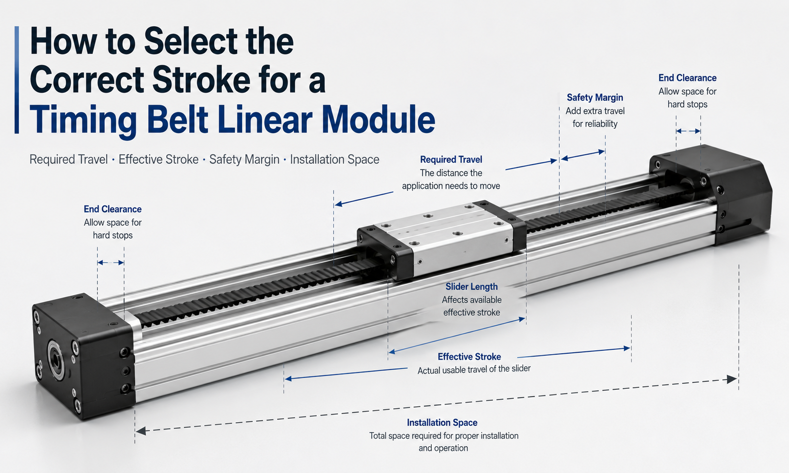
The stroke of a timing belt linear module determines how far the carriage can move along the axis. Selecting the correct stroke is not simply a matter of matching the module stroke to the required movement distance. Engineers must also consider the effective stroke, safety margin, carriage length, end clearance, installation space and long-stroke operating limitations.
If the selected stroke is too short, the carriage may reach the mechanical limit before completing the required process. If the stroke is unnecessarily long, the module may occupy more installation space, increase belt vibration and raise the overall system cost. A suitable stroke should provide enough usable travel while maintaining rigidity, speed, positioning stability and installation efficiency.
What Is the Stroke of a Timing Belt Linear Module?
The stroke of a timing belt linear module is the maximum linear travel available to the moving carriage between its allowable end positions. It is usually specified in millimeters and may also be described as travel length or working travel.
Stroke should not be confused with the total length of the linear module. The complete module also contains the carriage, pulley housings, motor mounting structure, tensioning components and end clearances. Therefore, the overall module length is always greater than the nominal stroke.
The relationship can be represented in simplified form as:
Overall Module Length ≈ Stroke + Carriage Length + End Structure Length
The exact dimensions depend on the module series, pulley arrangement, motor installation method and protective structure.
Required Travel and Effective Stroke
The first step in timing belt linear module stroke selection is determining the actual movement distance required by the application.
Required travelis the distance between the starting position and the final working position of the carriage. It should include all process positions, loading positions, unloading positions, inspection points and tool approach distances.
Effective strokeis the portion of the module stroke that can be safely used during normal operation. It excludes areas near the mechanical ends that should not be used as routine stopping positions.
A basic selection relationship is:
Selected Stroke ≥ Required Travel + Safety Margin
For example, if a pick-and-place mechanism requires a real movement distance of 1,200 mm, selecting a module with exactly 1,200 mm of stroke leaves no allowance for positioning adjustment, deceleration or installation deviation. A longer nominal stroke should normally be selected.
Why a Safety Margin Is Necessary
A timing belt module should not operate repeatedly at its absolute mechanical travel limit. A suitable safety margin helps prevent the carriage from contacting the end structure and provides space for deceleration, sensor installation and future position adjustment.
The safety margin may need to cover:
- Acceleration and deceleration distance
- Positioning tolerance
- Limit switch and sensor activation distance
- Mechanical assembly deviation
- Workpiece size variation
- Tool or gripper overhang
- Future process adjustment
For preliminary sizing, engineers may reserve a percentage of the required travel or add a fixed allowance at both ends. The final margin should be determined according to speed, acceleration, control method, payload and stopping accuracy.
High-speed applications generally require more deceleration distance than low-speed applications. Systems with large payloads or high inertia may also need additional end clearance.
How to Calculate the Recommended Stroke
A practical preliminary calculation can be expressed as:
Recommended Stroke = Required Travel + Left-End Margin + Right-End Margin
When the safety margin is specified as a percentage:
Recommended Stroke = Required Travel × (1 + Safety Margin Ratio)
Stroke Selection Example
Assume an automated transfer system has the following requirements:
- Required movement distance: 1,500 mm
- Left-end safety margin: 75 mm
- Right-end safety margin: 75 mm
The recommended minimum stroke is:
1,500 mm + 75 mm + 75 mm = 1,650 mm
If the manufacturer provides standard stroke increments, the next available standard stroke above 1,650 mm should be selected. For example, a 1,700 mm or 1,800 mm stroke may be appropriate depending on the product series.
Choosing the next larger standard stroke is generally safer than selecting a shorter stroke and operating close to the mechanical limits.
Consider the Carriage Length
The carriage length affects both the usable mounting area and the total length of the linear module. A longer carriage may improve load distribution and provide more space for mounting fixtures, robots, grippers or secondary axes. However, it also increases the overall installation length.
When determining the required installation envelope, engineers should consider:
- Nominal stroke
- Carriage length
- Drive-end housing length
- Tension-end housing length
- Motor and gearbox dimensions
- Coupling or motor adapter length
- Cable carrier bending radius
Two modules with the same nominal stroke may have different total lengths because their carriage and end structures are different. The dimensional drawing should always be checked before installation space is finalized.
Allow Sufficient End Clearance
End clearance is the reserved distance between the normal stopping position and the mechanical end of the module. This space helps protect the carriage, timing belt, pulley system and end components from impact.
The carriage should normally stop through programmed deceleration before reaching the mechanical limit. Limit sensors and software limits should be configured as protective measures rather than used as normal process stopping points.
When selecting end clearance, consider:
- Maximum operating speed
- Acceleration and deceleration settings
- Payload and moving mass
- Emergency stop distance
- Servo tuning performance
- Sensor response distance
- Controller positioning accuracy
A high-speed, heavy-load axis usually requires more stopping distance than a low-speed, light-load axis.
Check the Available Installation Space
Stroke selection must be coordinated with the actual machine layout. The module must fit within the available space not only during installation but also throughout its full operating cycle.
The installation space should include room for:
- The complete linear module body
- The motor and gearbox
- Cable carriers and pneumatic tubes
- Electrical connectors
- Mounting bolts and adjustment tools
- Lubrication and maintenance access
- Moving fixtures and workpieces
For compact machines, motor orientation can significantly affect the required space. Inline, folded or side-mounted motor configurations may be evaluated to reduce the total machine length.
When space is limited, the module should not be shortened by reducing the necessary safety margin. A different installation direction, carriage design or motor arrangement is usually a better solution.
Relationship Between Stroke and Timing Belt Length
As the stroke increases, the required timing belt length also increases. The belt travels around the drive pulley and tension pulley, with both ends connected to or acting on the moving carriage according to the module design.
A simplified belt-length concept is:
Timing Belt Length ≈ 2 × Pulley Center Distance + Pulley Wrap Length + Tensioning Allowance
The actual belt length must be calculated according to the pulley pitch diameter, belt routing, carriage connection method and tensioning structure. It should be confirmed using the manufacturer’s design data rather than estimated only from the nominal stroke.
A longer belt has greater elastic deformation. Under acceleration, deceleration and load changes, this deformation may influence positioning stability and settling time.
Long-Stroke Timing Belt Module Limitations
Timing belt linear modulesare well suited to long-stroke and high-speed applications, but increasing the stroke introduces additional engineering considerations.
1. Belt Elasticity
A longer timing belt can produce more elastic elongation under load. Although the belt teeth prevent ordinary transmission slip, belt stretch may still affect dynamic positioning accuracy and response.
2. Belt Vibration
Long unsupported belt sections may vibrate at high speed. Incorrect belt tension, rapid acceleration or unsuitable motion profiles can increase noise and vibration.
3. Structural Deflection
The aluminum profile or supporting beam may bend when the module becomes longer. The effect is more significant when the module is mounted horizontally with limited support points.
4. Reduced Allowable Acceleration
Long-stroke systems may require lower acceleration to control belt vibration, carriage impact and structural oscillation. Maximum speed and maximum acceleration should therefore be evaluated separately.
5. Positioning Stability
For extremely long travel or demanding positioning requirements, belt elasticity, frame deformation and thermal expansion may affect repeatability at different positions.
6. Cable Management
Long travel requires a longer cable carrier, electrical cable and pneumatic tube system. The additional drag force must be included in the moving load calculation.
7. Installation Alignment
A long module requires a straight and level mounting surface. Poor base flatness or incorrect alignment can increase guide resistance, noise and uneven wear.
Supporting Long-Stroke Modules
A long timing belt linear module should be supported according to the manufacturer’s recommended mounting intervals. Relying only on the two ends may cause profile deflection and reduce motion accuracy.
Common support methods include:
- Continuous support along the module base
- Multiple mounting points along the profile
- Installation on a rigid steel frame
- Additional support brackets for long spans
- Parallel modules for wide or heavy moving structures
The mounting surface should have adequate flatness, rigidity and strength. For gantry systems, the parallelism and height difference between the two axes must also be controlled.
Standard Stroke or Customized Stroke?
Many timing belt linear modules are available with configurable or customized stroke lengths. However, selecting a standard stroke can simplify manufacturing, delivery, replacement and future maintenance.
A standard stroke is often suitable when:
- The application layout can be adjusted slightly
- Fast delivery is important
- Future replacement should be convenient
- The machine uses standardized components
A customized stroke may be necessary when:
- Installation space is strictly limited
- The travel distance is unusually long
- The machine has a fixed structural envelope
- The module must match an existing production line
- Special carriage or end structures are required
Even for a customized module, sufficient end clearance and maintenance space should still be retained.
Stroke Selection for Different Applications
| Application | Stroke Selection Focus | Main Considerations |
|---|---|---|
| Pick and Place | Distance between pickup and placement points | Gripper width, acceleration distance and positioning margin |
| Material Transfer | Distance between production stations | Workpiece length, loading clearance and cycle time |
| Vision Inspection | Complete camera scanning range | Field of view, overlap distance and cable movement |
| Dispensing | Maximum processing area | Tool offset, path boundaries and deceleration space |
| Gantry Robot | Working width or length of the machine | Beam rigidity, dual-axis synchronization and end clearance |
| Packaging Equipment | Product transfer and positioning distance | Product size variation and production changeover |
Common Stroke Selection Mistakes
Selecting a Stroke Equal to the Required Travel
This leaves no safety margin for deceleration, sensor activation or installation adjustment.
Ignoring the Total Module Length
The nominal stroke does not include the complete carriage and end structures. The module may not fit into the planned machine space.
Using Mechanical Stops as Normal Stopping Positions
Frequent impact at the ends can damage the carriage, belt connection, bearings and pulley components.
Ignoring Tool and Workpiece Dimensions
The carriage position alone may not represent the full movement envelope. Grippers, fixtures and workpieces may extend beyond the carriage.
Assuming Every Long Stroke Can Run at Maximum Acceleration
The module may be capable of high speed but require reduced acceleration because of belt vibration, frame rigidity or moving load.
Failing to Reserve Maintenance Space
Insufficient access can make belt tension adjustment, motor replacement and sensor maintenance difficult.
Timing Belt Linear Module Stroke Selection Process
- Identify all required working positions.
- Calculate the maximum distance between the extreme positions.
- Include tool, fixture and workpiece overhang.
- Add acceleration, deceleration and positioning margins.
- Select the next suitable standard or customized stroke.
- Calculate the complete module installation length.
- Check motor, gearbox and cable carrier space.
- Evaluate belt vibration and structural rigidity for long strokes.
- Confirm payload, speed, acceleration and positioning requirements.
- Verify the final dimensions using the manufacturer’s technical drawing.
Frequently Asked Questions
Is the module stroke the same as the effective working distance?
Not always. The nominal stroke is the available mechanical travel, while the effective working distance should exclude the safety clearance reserved near both ends.
How much safety margin should be added to the required travel?
The margin depends on speed, acceleration, payload, stopping accuracy and sensor arrangement. It may be added as a fixed distance at each end or as a percentage of the required travel. High-speed and high-inertia systems normally need a larger margin.
Can a timing belt module be manufactured with a customized stroke?
Yes. Many timing belt modules can be produced with customized profile and belt lengths. The maximum practical stroke still depends on profile rigidity, belt behavior, load, speed and mounting conditions.
Does a longer stroke reduce positioning accuracy?
A longer stroke does not automatically cause poor positioning, but belt elasticity, structural deflection, vibration and thermal expansion become more significant as the travel increases. These factors must be considered during system design.
Should the carriage stop at the mechanical end of the module?
No. The normal stopping position should remain inside the mechanical limit. Software limits, limit switches and programmed deceleration should prevent the carriage from contacting the end structure.
What information is required when ordering a long-stroke module?
Important information includes required travel, payload, mounting direction, speed, acceleration, positioning requirements, duty cycle, motor arrangement, installation space and support conditions.
Conclusion
Correct timing belt linear module stroke selection starts with the real movement distance, but it must also account for safety margins, carriage dimensions, end clearance and the complete installation envelope. For long-stroke applications, belt elasticity, vibration, profile deflection, cable management and mounting support must be evaluated together.
A reliable selection method is to calculate the required travel, add suitable margins at both ends, choose the next appropriate standard stroke and then verify the full module dimensions using the technical drawing. This approach helps prevent insufficient travel, mechanical impact, installation interference and unnecessary system length.
