 English

A timingbelt linear modulecan be installed vertically, but vertical operation requires more careful selection than horizontal motion. In a vertical axis, the motor must overcome gravity during upward movement and control the descending load during downward movement. The system must also prevent the carriage and payload from falling when the motor stops, the servo loses power or the timing belt fails.
For this reason, a vertical timing belt linear module normally requires a brake motor, sufficient motor torque, an appropriate safety factor and reliable falling-prevention measures. Counterbalance devices may also be used when the payload is heavy or the axis operates at high frequency.
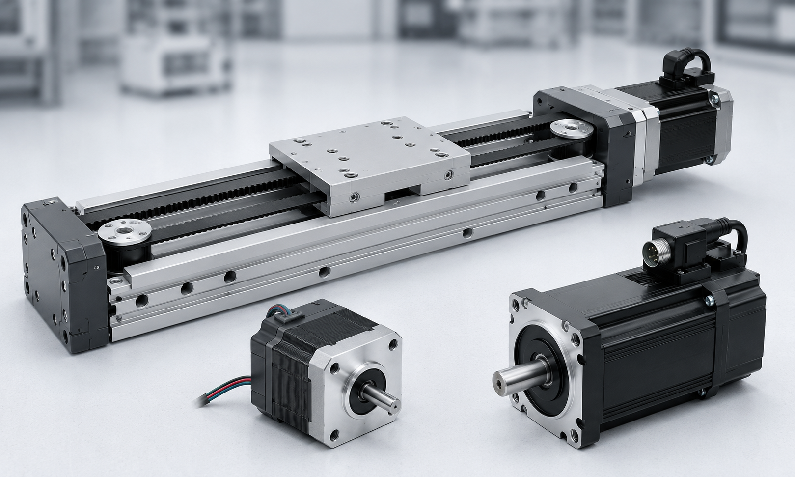
Can a Timing Belt Linear Module Be Installed Vertically?
Yes. Timing beltlinear modulesare widely used as vertical lifting axes in pick-and-place systems, packaging equipment, loading and unloading machines,gantry robots, inspection equipment and automated production lines.
However, not every timing belt module is automatically suitable for vertical installation. The following conditions must be checked before selection:
- The timing belt must have sufficient tensile strength.
- The motor must provide enough torque to lift the load against gravity.
- The motor should include an electromagnetic brake.
- The guide rail and carriage must withstand the applied load and moment.
- The structure should include power-off protection and falling-prevention measures.
- The selected load should remain below the module’s permitted vertical load.
- The acceleration, speed, stroke and operating frequency must be considered together.
A module with a high horizontal load rating may have a much lower allowable load when installed vertically because gravity continuously acts on the moving assembly.
How Vertical Installation Differs from Horizontal Installation
In a horizontal application, gravity is mainly supported by the linear guide. The motor primarily overcomes acceleration force, friction and external process resistance.
In a vertical application, the motor must continuously support or control the weight of the carriage, tooling and payload. The force required for upward acceleration is therefore significantly higher.
| Selection Factor | Horizontal Axis | Vertical Axis |
|---|---|---|
| Gravity influence | Mainly carried by the guide | Acts directly against the drive system |
| Motor brake | Usually optional | Normally required |
| Power-off risk | Carriage normally remains in position | Carriage may fall |
| Motor torque | Based mainly on acceleration and friction | Must include gravity, acceleration and friction |
| Safety design | Standard motion protection | Brake, mechanical stop and anti-fall protection |
| Counterbalance | Rarely required | Useful for heavy or high-cycle loads |
Calculate the Vertical Axis Load
The moving mass of a vertical timing belt module includes more than the customer’s payload. The total moving mass should include:
- Workpiece or product weight
- Fixture, gripper or tooling weight
- Moving carriage weight
- Mounted sensors, cables and brackets
- Any additional moving mechanism
The basic gravity force is calculated as:
Fg= m × g
Where:
- Fgis the gravity force in newtons.
- mis the total moving mass in kilograms.
- gis gravitational acceleration, approximately 9.81 m/s².
For example, if the complete moving mass is 20 kg:
Fg= 20 × 9.81 = 196.2 N
The motor must provide more than 196.2 N because additional force is required for acceleration, friction and transmission losses.
Force Required During Upward Acceleration
The approximate upward driving force can be calculated as:
Fup= m × (g + a) + Ff+ Fe
Where:
- ais the upward acceleration.
- Ffis the estimated friction resistance.
- Feis any additional external process force.
The design force should then include a safety factor:
Fdesign= Fup× S
For a typical vertical axis, a safety factor of 1.5 to 2.0 is commonly considered. A larger factor may be necessary for shock loads, frequent starts and stops, uncertain payloads or safety-critical equipment.
Force During Downward Movement
Gravity assists downward movement, but this does not mean that downward operation requires no motor torque. The motor must control the descending mass and prevent overspeed.
During rapid deceleration, the motor may operate in a regenerative condition. The servo drive may therefore require a braking resistor or regenerative unit, especially when the moving mass, speed or stroke is large.
Motor Torque Calculation
After determining the required linear force, the torque at the timing pulley can be estimated using:
Tpulley= Fdesign× r ÷ n
Where:
- Tpulleyis the required pulley torque.
- ris the pitch radius of the timing pulley.
- oris the transmission efficiency.
If a gearbox is used, the required motor torque can be estimated as:
Tmotor= Tpulley÷ (i × ng)
Where:
- iis the gearbox reduction ratio.
- orgis the gearbox efficiency.
Motor selection should not be based only on rated torque. The following values should also be checked:
- Rated motor torque
- Peak motor torque
- Required acceleration torque
- Maximum operating speed
- Motor inertia and load inertia ratio
- RMS torque over the complete operating cycle
- Regenerative energy during downward deceleration
- Brake holding torque
A servo motor is generally preferred for vertical timing belt applications because it provides controlled acceleration, accurate positioning, speed monitoring and overload protection.
Why a Vertical Axis Needs a Brake Motor
An electromagnetic motor brake is one of the most important components in a vertical motion system. When the servo is disabled or the power supply is interrupted, gravity may cause the carriage to move downward. The brake holds the motor shaft and helps keep the vertical axis in position.
The brake should be a normally closed, spring-applied and electrically released design. This means that the brake engages automatically when electrical power is removed.
The required static holding torque at the pulley can be estimated as:
Thold= m × g × r ÷ n
A holding safety factor should then be applied:
Tbrake≥ Thold× Sb
The selected brake torque should exceed the calculated holding torque. The brake must also account for the carriage, tooling and all other moving components.
Important:A standard servo motor brake is normally designed for static holding, not for repeatedly stopping a moving load. Normal deceleration should be completed by the motor before the brake engages.
Recommended Brake Control Sequence
- Enable the servo and establish motor holding torque.
- Release the electromagnetic brake.
- Confirm brake release before starting motion.
- Complete the movement and stop the axis using the servo motor.
- Command the brake to engage.
- Confirm that the brake is engaged.
- Disable the servo only after the brake has secured the load.
A delay should be included in the control program to account for the mechanical opening and closing time of the brake.
Counterbalance Options for Vertical Motion
A counterbalance reduces the effective gravity load acting on the motor. It can lower motor torque, reduce energy consumption, decrease brake wear and improve vertical axis stability.
Common counterbalance methods include:
Counterweight
A counterweight is connected to the moving carriage through a belt, pulley or cable system. It can offset a large portion of the moving mass.
Counterweights are effective for long strokes and heavy loads, but they require additional installation space and increase the total moving inertia of the system.
Gas Spring
A gas spring can provide an upward supporting force in compact vertical mechanisms. It is relatively simple, but its force changes with stroke and may not remain constant throughout the complete travel.
Pneumatic Cylinder
A pneumatic cylinder can be used as a balancing cylinder. The air pressure can be adjusted according to the vertical load.
This method is suitable for machines that already have a stable compressed-air supply. Pressure loss and air leakage must be considered in the safety design.
Constant-Force Spring
A constant-force spring can provide approximately uniform supporting force over its working stroke. It is often used for relatively light vertical axes and compact equipment.
The balancing force should not normally exceed the total gravity force. Excessive counterbalance may cause the carriage to rise when the motor is disabled.
Timing Belt Tension in a Vertical Module
Correct timing belt tension is essential for vertical operation. If the belt tension is too low, the system may experience:
- Tooth jumping during acceleration or emergency stopping
- Positioning errors
- Vibration and abnormal noise
- Unstable downward movement
- Reduced transmission stiffness
If the belt tension is too high, it may cause:
- Excessive motor load
- Increased pulley bearing load
- Higher friction and temperature
- Accelerated belt and bearing wear
- Reduced service life
Belt tension should follow the module manufacturer’s specified value. It should not be increased arbitrarily to compensate for insufficient motor torque or an undersized belt.
The belt width, tooth profile, reinforcement material and allowable tensile load must all be suitable for the vertical design force.
Power-Off Protection and Falling Prevention
A motor brake alone may not provide sufficient protection for every vertical application. The appropriate safety level depends on the moving mass, installation height, operating environment and consequences of an uncontrolled fall.
Possible falling-prevention measures include:
- Normally closed motor brake
- Mechanical anti-fall device
- Safety brake mounted on the guide rail
- Ratchet or locking mechanism
- Counterbalance system
- Mechanical end stops
- Energy-absorbing buffers
- Safety catch or secondary support
- Redundant belt or lifting mechanism
- Servo alarm and brake-status monitoring
Where personnel may enter the area beneath the vertical axis, the system should not rely only on the motor brake. A risk assessment and an independent mechanical holding device may be required.
Protection Against Belt Failure
Although a correctly selected timing belt has a long service life, belt wear, incorrect tension, contamination, pulley misalignment or overload can eventually cause failure.
For equipment in which belt failure could create a serious hazard, consider:
- A dual-belt arrangement
- A secondary safety cable
- A guide-rail safety brake
- A mechanical locking pin
- Scheduled belt inspection and replacement
- A protective enclosure that prevents access below the axis
Guide Rail and Moment Load Considerations
The vertical payload should be positioned as close as possible to the center of the carriage. An offset payload produces moment loads on the linear guide.
The main moments normally checked are:
- Pitching moment
- Yawing moment
- Rolling moment
A lightweight payload located far from the carriage may create a larger guide load than a heavier payload installed close to the carriage center.
When the tooling has a large overhang, consider using:
- A longer carriage
- Two guide blocks
- A wider module
- Two parallel vertical modules
- An external guide structure
Vertical Installation Design Requirements
The module should be mounted to a rigid and flat machine frame. Insufficient frame stiffness can cause vibration, guide misalignment and poor positioning accuracy.
During installation:
- Make sure the module is aligned vertically.
- Support the module along the recommended mounting surfaces.
- Tighten mounting bolts using the specified sequence and torque.
- Avoid twisting the aluminum profile.
- Provide flexible cable guidance for the moving carriage.
- Keep cables from pulling the carriage downward or sideways.
- Install upper and lower limit sensors.
- Set software travel limits inside the mechanical limits.
- Provide sufficient deceleration distance before the end stops.
- Install mechanical buffers for abnormal overtravel.
Vertical Timing Belt Module Selection Procedure
- Calculate the total moving mass.Include the payload, fixture, carriage and all moving accessories.
- Define the stroke.Add safety margins and deceleration distance to the required travel.
- Determine speed and acceleration.Use the actual motion profile rather than only the maximum machine speed.
- Calculate upward driving force.Include gravity, acceleration, friction and external resistance.
- Apply a safety factor.Increase the factor for shock loads or uncertain operating conditions.
- Check the belt capacity.Verify allowable tension, tooth strength and belt width.
- Calculate pulley torque.Use the pulley pitch radius and transmission efficiency.
- Select the motor and gearbox.Check rated torque, peak torque, speed, inertia and RMS torque.
- Select the motor brake.Make sure the brake holding torque exceeds the gravity holding requirement.
- Check the guide load and moments.Include payload overhang and tooling dimensions.
- Evaluate regenerative energy.Add a braking resistor or regenerative unit when necessary.
- Design anti-fall protection.Select protection according to the machine risk assessment.
- Verify operating life.Consider cycle frequency, daily operating hours and expected maintenance intervals.
Vertical Axis Calculation Example
Consider a vertical timing belt module with the following conditions:
- Total moving mass: 20 kg
- Upward acceleration: 1.5 m/s²
- Estimated friction resistance: 50 N
- External process force: 0 N
- Safety factor: 1.5
- Pulley pitch radius: 25 mm, or 0.025 m
- Transmission efficiency: 90%
The upward force is:
Fup = 20 × (9.81 + 1.5) + 50
Fup= 276.2 N
After applying the safety factor:
Fdesign= 276.2 × 1.5 = 414.3 N
The required pulley torque is:
Tpulley = 414.3 × 0.025 ÷ 0.90
Tpulley≈ 11.5 N·m
The static gravity holding torque is:
Thold = 20 × 9.81 × 0.025 ÷ 0.90
Thold≈ 5.45 N·m
The selected motor, gearbox and brake must be checked against these values. The final selection must also consider operating speed, peak torque, motor inertia, cycle time and regenerative energy.
Common Vertical Installation Mistakes
Selecting the Motor Only by Payload
The payload alone does not represent the complete moving mass. Ignoring the carriage, tooling and accessories can lead to insufficient motor torque.
Using a Motor Without a Brake
A servo motor can hold position while energized, but it cannot guarantee holding when power is removed. A vertical axis should normally use a brake motor.
Treating the Brake as an Emergency Stop
Repeatedly using a holding brake to stop a moving axis can cause rapid wear and brake failure. The servo should stop the motion before the brake engages.
Ignoring Downward Regeneration
A heavy vertical load can return energy to the servo drive during descent. Without suitable regenerative capacity, the drive may produce an overvoltage alarm.
Increasing Belt Tension Excessively
Excessive pretension cannot correct an undersized belt or motor. It increases bearing load and may shorten the module’s service life.
Relying Only on Software Limits
Software limits cannot protect the machine during controller failure, sensor failure or power loss. Mechanical limits and buffers should also be provided.
Ignoring Payload Overhang
An offset fixture can create excessive moment load even when the payload weight is within the nominal rating.
Frequently Asked Questions
Can a timing belt module hold a vertical load without power?
Only when a suitable brake or mechanical holding device is provided. The servo motor itself cannot reliably hold the load after power is removed.
Is a stepper motor suitable for a vertical timing belt axis?
A stepper motor may be used for light and low-speed vertical loads, but it should include a brake and sufficient torque margin. A servo motor is generally preferred for higher speed, heavier loads and applications requiring position feedback.
Does every vertical axis need a counterbalance?
No. A counterbalance is optional when the motor and brake can safely handle the load. It becomes more useful for heavy payloads, long strokes, high cycle rates or energy-sensitive equipment.
What safety factor should be used?
A factor of approximately 1.5 to 2.0 is often considered for preliminary selection. The actual factor should be determined according to load uncertainty, shock, operating frequency and machine safety requirements.
Can the motor brake stop the axis during an emergency?
A standard motor brake is mainly intended to hold a stationary load. Emergency stopping should normally be handled by the servo drive, a dedicated safety brake or another appropriately rated stopping device.
How can a vertical module be prevented from falling if the belt breaks?
High-risk systems may use a guide-rail safety brake, secondary cable, redundant belt, mechanical locking mechanism or protective enclosure. The appropriate method should be selected through a machine risk assessment.
Conclusion
A timing belt linear module can provide fast, long-stroke and accurate vertical motion when it is correctly selected. The design must account for the total moving mass, gravity force, acceleration, pulley torque, belt capacity, guide moments and regenerative energy.
A brake motor is normally essential, but the brake should not be treated as the only safety device. For heavy loads or applications where falling could cause injury or equipment damage, counterbalance systems and independent mechanical anti-fall protection should also be considered.
By combining accurate load calculations, sufficient safety margins, correct belt tension and reliable power-off protection, a vertical timing belt module can operate safely and consistently throughout its intended service life.
