 English

Atiming belt linear moduleis a high-speed linear motion unit designed to move loads over medium or long distances through a toothed belt and pulley transmission system. It combines a timing belt, drive pulley, idler pulley, linear guide, carriage, aluminum profile, bearings, motor interface and tensioning mechanism into a complete linear axis.
When engineers select a timing beltlinear module, they should not evaluate only one specification such as maximum speed or payload. The actual performance of the module depends on the combined relationship between load, stroke length, acceleration, mounting orientation, duty cycle, positioning requirements, motor capacity and allowable load moments.
For example, a module may be capable of reaching a high no-load speed, but that speed may need to be reduced when the carriage carries a heavy payload or operates over a long stroke. Similarly, a module with sufficient vertical payload capacity may still be unsuitable if the application produces an excessive overturning moment on the carriage.
This guide explains the most importanttiming belt linear module specifications, including payload, stroke length, maximum speed, acceleration, repeatability, positioning accuracy, belt width, pulley diameter, motor power and static allowable load moments.
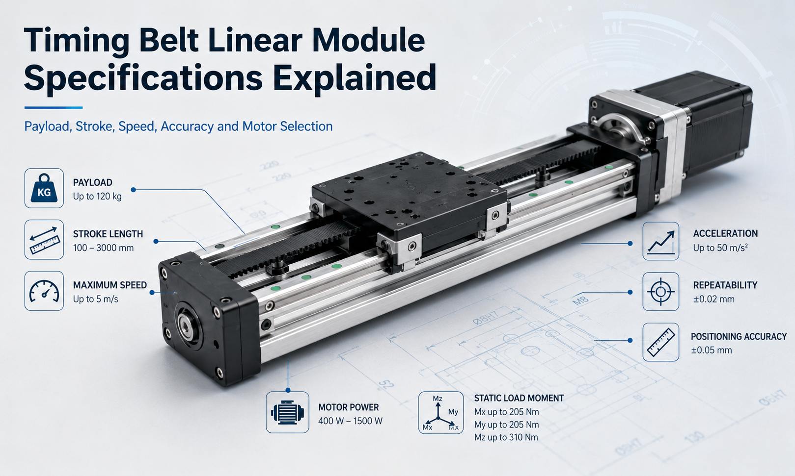
Overview of Timing Belt Linear Module Specifications
The technical specifications of a belt driven linear module describe its mechanical capacity, motion performance and operating limitations. These values help engineers determine whether the module can safely and accurately complete the required movement.
| Specification | What It Describes | Why It Matters |
|---|---|---|
| Payload | The load that the carriage can support and move | Affects guide life, acceleration, motor size and safety |
| Stroke Length | The usable linear travel distance | Determines whether the module can cover the required workspace |
| Maximum Speed | The highest allowable carriage travel speed | Affects cycle time and production throughput |
| Acceleration | The rate at which the carriage changes speed | Influences cycle time, dynamic force and vibration |
| Repeatability | The ability to return to the same position repeatedly | Important for repetitive automation processes |
| Positioning Accuracy | The difference between the commanded and actual position | Determines absolute positioning performance |
| Belt Width | The width of the toothed timing belt | Affects transmission force, stiffness and load capacity |
| Pulley Diameter | The pitch diameter of the drive and idler pulleys | Influences speed, torque, belt bending and resolution |
| Motor Power | The motor output required to drive the axis | Determines available torque, speed and acceleration |
| Static Load Moment | The allowable overturning or twisting moment on the carriage | Prevents guide overload and premature wear |
Payload Capacity
Payloadis one of the first specifications engineers review when selecting a timing belt linear module. It refers to the total mass that the carriage can safely support and move under specified operating conditions.
The payload usually includes more than the workpiece itself. Engineers should calculate the combined mass of all components mounted on the carriage, including:
- Workpieces or products being transported
- Grippers, vacuum cups or clamps
- Tooling plates and mounting brackets
- Sensors, cameras or inspection equipment
- Cables, cable chains and pneumatic tubing
- Additional axes mounted on the carriage
The allowable payload varies according to the installation orientation. A module installed horizontally primarily supports the load through its guide rail system. In a vertical installation, the motor and belt transmission must also overcome gravity, which increases the required motor torque and may require a brake to prevent the carriage from falling during power loss.
Horizontal and Vertical Payload
Manufacturers may specify different payload ratings for horizontal, vertical and wall-mounted installations. These values should not be treated as interchangeable.
In horizontal applications, the motor mainly overcomes acceleration force, friction and external process resistance. In vertical applications, the motor must continuously support the gravitational force of the payload in addition to producing acceleration.
A vertical axis should therefore be evaluated using the actual moving mass, upward acceleration, downward deceleration, motor brake capacity and emergency-stop requirements.
Dynamic Payload Versus Static Payload
Static payload describes the load supported while the carriage is stationary. Dynamic payload describes the load that can be moved repeatedly while maintaining the required speed, acceleration, guide life and positioning stability.
A carriage may support a relatively large static load but require a lower operating load during high-speed reciprocating motion. For this reason, dynamic operating conditions are usually more important than the simple static weight of the mounted equipment.
Stroke Length
Stroke lengthis the usable distance through which the carriage can travel.Timing belt modulesare especially suitable for long-stroke applications because they are not limited by the critical rotational speed of a long ball screw.
Depending on the module size, belt construction, profile stiffness and application requirements, a belt driven linear module may support strokes ranging from several hundred millimeters to several meters.
When specifying the required stroke, engineers should distinguish between the following dimensions:
- Effective stroke:the usable movement distance of the carriage
- Module length:the total physical length of the complete axis
- Safety allowance:additional travel reserved for deceleration and limit protection
- Overtravel distance:the mechanical distance available beyond the normal operating range
The total module length is always greater than the effective stroke because space is required for the carriage, end blocks, pulleys, bearings, tensioning mechanism and motor connection.
Long-Stroke Design Considerations
Increasing the stroke length affects more than the physical size of the module. A long axis may also require evaluation of:
- Aluminum profile deflection
- Belt vibration and belt tension
- Guide rail alignment
- Mounting support spacing
- Cable chain length
- Thermal expansion
- Maximum operating speed
For very long strokes, the module base should be supported at multiple mounting points. Insufficient support can cause profile bending, guide misalignment, vibration and reduced positioning stability.
Maximum Speed
Maximum speedindicates the highest allowable carriage travel velocity under defined operating conditions. High speed is one of the main advantages of timing belt linear modules.
Compared with many ball screw driven systems, a timing belt module can achieve high linear velocity over a long travel distance without the limitations associated with screw whip or critical screw speed.
However, the catalog maximum speed is not always the recommended continuous operating speed. The achievable value depends on:
- Moving payload
- Stroke length
- Belt pitch and belt width
- Pulley diameter
- Motor maximum speed
- Acceleration and deceleration distance
- Guide rail lubrication
- Module mounting rigidity
- Duty cycle
- Required service life
A module may reach its rated maximum speed with a light load and moderate acceleration, while a heavier load may require a lower speed to reduce belt tension, vibration and motor demand.
Speed and Cycle Time
Maximum speed alone does not determine the total cycle time. In short-stroke applications, the carriage may not have enough distance to accelerate to the specified top speed before it must begin decelerating.
For these applications, acceleration performance can have a greater effect on cycle time than maximum velocity. Engineers should evaluate the complete motion profile rather than selecting the axis solely from the catalog speed rating.
Acceleration
Accelerationdescribes how quickly the carriage increases or decreases its speed. A higher acceleration can shorten machine cycle time, especially in pick-and-place, packaging, sorting and material-handling applications involving frequent reciprocating movements.
Acceleration also produces dynamic force. The basic relationship can be expressed as:
Dynamic force = Moving mass × Acceleration
As the payload or acceleration increases, the belt, pulleys, bearings, guide blocks, carriage and motor must withstand greater force. Excessive acceleration may cause:
- Belt tooth deformation or tooth jumping
- Carriage vibration
- Motor overload alarms
- Reduced positioning stability
- Loose fasteners
- Increased guide and bearing wear
- Structural resonance
Acceleration should therefore be selected according to the real payload, stroke, machine rigidity and process requirements. Using a smooth S-curve motion profile can reduce mechanical shock compared with an abrupt trapezoidal profile.
Repeatability
Repeatabilityis the ability of the carriage to return to the same commanded position during repeated movements under the same conditions. It is one of the most important performance indicators for repetitive industrial automation.
Repeatability is commonly tested by moving the carriage to the same target position multiple times and measuring the variation between the actual stopping positions.
The repeatability of a timing belt linear module is influenced by:
- Belt stiffness and tooth engagement
- Belt tension consistency
- Gearbox backlash
- Pulley machining accuracy
- Motor encoder resolution
- Guide rail clearance
- Control system tuning
- Payload variation
- Temperature change
- Approach direction
For many packaging, transfer, loading and sorting systems, repeatability is more important than absolute positioning accuracy because the carriage repeatedly moves between previously taught positions.
Unidirectional and Bidirectional Repeatability
Unidirectional repeatability is measured when the carriage approaches the target from the same direction each time. Bidirectional repeatability is measured when the target is approached from both directions.
Bidirectional repeatability may be less precise because belt elasticity, transmission clearance and load direction can affect the final stopping position. Applications requiring high bidirectional consistency should use properly tensioned belts, low-backlash reducers and optimized servo control.
Positioning Accuracy
Positioning accuracydescribes how closely the actual carriage position matches the commanded position across the operating stroke.
Repeatability and positioning accuracy are related but not identical. A module may repeatedly return to the same location while still having a consistent offset from the commanded coordinate. In this case, repeatability may be good even though absolute positioning accuracy is limited.
Positioning accuracy can be affected by:
- Belt pitch error
- Pulley pitch diameter tolerance
- Belt elastic elongation
- Thermal expansion
- Control resolution
- Encoder feedback
- Module straightness
- Installation alignment
- Load variation
- Mechanical compliance
Timing belt linear modules are generally selected for high speed and long stroke rather than ultra-high absolute accuracy. Applications such as precision machining, semiconductor alignment or micron-level measurement may require a ball screw or linear motor system instead.
Where better absolute accuracy is needed, engineers can use external linear encoders, calibration tables, laser measurement and software compensation to reduce systematic positioning errors.
Timing Belt Width
Belt widthdirectly affects the transmission capacity and stiffness of the timing belt drive. A wider belt generally supports greater tensile force and provides higher resistance to elastic elongation.
Belt width should be selected according to:
- Payload
- Acceleration
- Required driving force
- Stroke length
- Duty cycle
- Pulley diameter
- Expected service life
- Safety factor
A belt that is too narrow may stretch excessively, reduce positioning stability or experience premature tooth wear. A belt that is unnecessarily wide increases pulley size, module dimensions, inertia and cost.
The belt material and reinforcement also matter. Timing belts may use steel cords, aramid fibers or other tensile members to improve stiffness and reduce elongation under load.
Pulley Diameter
Pulley diameterinfluences linear speed, motor torque, belt bending stress and positioning resolution. For each motor revolution, a larger pulley moves the belt a greater linear distance.
A larger drive pulley can therefore increase linear travel per motor revolution and support higher speed at the same motor rotational speed. However, it also requires more motor torque to generate the same linear driving force.
A smaller pulley improves mechanical force multiplication and movement resolution, but excessive belt bending around a very small pulley can reduce belt life. The selected pulley diameter must therefore remain within the minimum bending requirements of the belt manufacturer.
Relationship Between Pulley Diameter and Linear Travel
The approximate linear travel per pulley revolution is determined by the pulley pitch circumference. In a toothed belt system, it can also be calculated from the belt pitch multiplied by the number of pulley teeth.
Linear travel per revolution = Belt pitch × Number of pulley teeth
This relationship is important when calculating commanded movement, motor speed and system resolution.
Motor Power and Torque
Motor powermust be sufficient to accelerate the moving mass, overcome friction, resist process forces and maintain the required speed. Timing belt modules are commonly driven by servo motors or stepper motors.
The required motor size depends on:
- Total moving mass
- Installation orientation
- Target speed
- Acceleration and deceleration
- Pulley diameter
- Gear ratio
- External process force
- Mechanical efficiency
- Duty cycle
- Safety factor
Motor power should not be selected only from the payload value. A light load moving at very high acceleration may require more peak torque than a heavier load moving slowly.
Continuous Torque and Peak Torque
Continuous torque is the torque the motor can deliver over a sustained period without overheating. Peak torque is available for short acceleration or deceleration periods.
The motion cycle should be analyzed to ensure that peak torque remains within the motor and drive limits and that the root mean square torque does not exceed the continuous rating.
Servo Motor Versus Stepper Motor
Servo motors are generally preferred for high-speed, high-acceleration and closed-loop positioning applications. They provide encoder feedback, high-speed torque and improved control over changing loads.
Stepper motors may be suitable for lower-speed, moderate-load applications where cost and control simplicity are more important. However, an undersized stepper motor can lose steps during rapid acceleration or unexpected resistance.
Static Allowable Load Moments
Payload capacity alone is not sufficient to evaluate a linear module. Engineers must also examine thestatic allowable load momentsacting on the carriage.
A load mounted away from the carriage center creates a lever arm. Even when the total weight is within the payload limit, a large offset can generate an excessive moment on the guide blocks.
Allowable moment ratings are commonly divided into three directions:
- Pitch moment:forward or backward rotation around the transverse axis
- Yaw moment:left or right rotation around the vertical axis
- Roll moment:twisting rotation around the direction of travel
The approximate static moment can be calculated as:
Load moment = Applied force × Distance from the reference center
For example, mounting a heavy tool far above the carriage creates a larger overturning moment than mounting the same tool close to the carriage surface.
Reducing Load Moments
Excessive moments can be reduced by:
- Positioning the load closer to the carriage center
- Using a larger carriage or longer guide block spacing
- Adding a second parallel linear module
- Supporting the load with an external guide
- Reducing acceleration
- Using a wider mounting plate
- Distributing the load across multiple carriages
When multiple forces and moments act simultaneously, the combined load ratio should be evaluated according to the manufacturer’s calculation method.
Factors That Change Published Specifications
Catalog values are usually based on defined test conditions. Actual allowable performance may be lower when the operating environment or installation differs from those conditions.
Important derating factors include:
- Vertical or inclined installation
- Long unsupported stroke
- High ambient temperature
- Continuous high-duty operation
- Dust, moisture or chemical contamination
- Shock loads and external vibration
- Offset payloads
- Frequent emergency stops
- Insufficient lubrication
- Poor mounting surface flatness
For demanding applications, engineers should apply an appropriate safety factor rather than operating continuously at every maximum catalog value.
How to Select the Correct Specifications
A practical timing belt linear module selection process should follow a complete operating profile rather than a single specification.
- Calculate the total moving mass, including tooling and cables.
- Define the effective stroke and required safety allowance.
- Determine the mounting orientation.
- Define the target cycle time, speed and acceleration.
- Calculate external forces and carriage load moments.
- Determine the required repeatability and positioning accuracy.
- Select a suitable belt width and pulley configuration.
- Calculate motor speed, continuous torque and peak torque.
- Check module rigidity, support spacing and guide life.
- Apply safety factors for duty cycle and environmental conditions.
The selected model should satisfy all of these conditions simultaneously. A module that meets the payload requirement but fails the moment, speed or motor torque requirement is not a suitable solution.
Example Specification Evaluation
Consider an automated transfer system that moves a 20 kg fixture over a 2,000 mm stroke. The carriage must reach a high travel speed and repeatedly stop at several loading positions.
The engineer should not simply select a module rated for more than 20 kg. The evaluation should also include:
- The weight of the fixture, product, cables and mounting plate
- The acceleration required to achieve the target cycle time
- The distance available for acceleration and deceleration
- The effect of the 2,000 mm stroke on belt vibration
- The offset between the payload center and carriage center
- The required repeatability at each loading position
- The motor speed required by the pulley diameter
- The peak torque during acceleration
- The support spacing beneath the aluminum profile
This complete evaluation provides a more reliable result than comparing only payload and maximum speed values.
Timing Belt Module Specifications Versus Ball Screw Module Specifications
| Parameter | Timing Belt Linear Module | Ball Screw Linear Module |
|---|---|---|
| Stroke Length | Well suited to long strokes | Usually more limited by screw length and critical speed |
| Maximum Speed | Generally high | Moderate to high depending on screw lead and length |
| Acceleration | High due to low moving transmission mass | May be limited by screw inertia |
| Repeatability | Suitable for general industrial automation | Usually better for precision positioning |
| Positioning Accuracy | Moderate | Generally higher |
| Maintenance | Relatively simple | Requires proper screw lubrication |
| Typical Applications | Transfer, packaging, sorting and long-stroke motion | Machining, assembly and precision positioning |
Common Specification Selection Mistakes
Selecting Only by Maximum Payload
Maximum payload does not account for load offset, acceleration, orientation or carriage moment. The complete load condition must be calculated.
Using Maximum Speed as the Continuous Speed
Operating continuously at the catalog maximum may increase vibration, heat and wear. A practical operating margin should be maintained.
Ignoring Acceleration Distance
A high maximum speed may provide little benefit when the stroke is too short for the carriage to reach that speed.
Confusing Repeatability with Positioning Accuracy
A module can have good repeatability but still show an absolute position error. The application must define which performance characteristic is more important.
Ignoring Load Moments
An offset load can overload the guide system even when the total payload is below the rated limit.
Undersizing the Motor
A motor selected only from continuous running force may not provide enough peak torque for rapid acceleration or emergency deceleration.
Frequently Asked Questions
What is the maximum speed of a timing belt linear module?
The maximum speed depends on the module size, belt type, pulley diameter, stroke, payload, motor speed and installation rigidity. The catalog value should always be verified against the actual operating conditions.
How long can the stroke of a belt driven linear module be?
Timing belt modules can support relatively long strokes, often extending to several meters. The practical limit depends on profile stiffness, belt vibration, guide alignment and mounting support.
Does a wider timing belt increase load capacity?
A wider belt generally increases tensile capacity and transmission stiffness. However, guide capacity, carriage moments, bearings and motor torque must also support the increased load.
Is repeatability the same as positioning accuracy?
No. Repeatability measures the variation when returning to the same position, while positioning accuracy measures the difference between the commanded and actual position.
Can a timing belt linear module be installed vertically?
Yes, but the motor must support the payload against gravity. Vertical applications may also require a brake, counterbalance or anti-fall mechanism.
How should motor power be selected?
Motor selection should consider moving mass, acceleration, maximum speed, pulley diameter, installation orientation, external force, duty cycle and mechanical efficiency. Both peak torque and continuous torque must be checked.
Conclusion
Understandingtiming belt linear module specificationsis essential for selecting a reliable and efficient linear motion system. Payload, stroke length, maximum speed, acceleration, repeatability and positioning accuracy describe different aspects of module performance and must be evaluated together.
Belt width and pulley diameter determine much of the transmission capacity and motion relationship, while motor power controls the available speed and acceleration. Static allowable load moments are equally important because an offset load can overload the guide system even when the total payload remains within the nominal limit.
A correctly selected timing belt linear module should satisfy the complete motion profile, including load, orientation, travel distance, cycle time, precision, installation rigidity and operating environment. By evaluating these parameters as an integrated system, engineers can achieve faster cycles, stable positioning, longer service life and more reliable industrial automation.
