 English

Gantry automation systems are widely used for material handling, pick-and-place operations, machine loading, assembly, inspection, dispensing and large-format processing. These systems normally combine two or more linear motion axes to move an end effector across a defined working area.
A timing beltlinear moduleis particularly suitable for gantry systems that require long travel, high operating speed and frequent reciprocating motion. Its lightweight transmission structure allows the moving carriage to travel rapidly without the critical-speed limitations commonly associated with long ball screws.
However, a reliable timing belt gantry system requires more than selecting individual linear modules. Engineers must evaluate the gantry structure, dual-axis synchronization, crossbeam load, positioning repeatability, cable routing and end-effector integration as a complete motion system.
What Is a Timing Belt Gantry System?
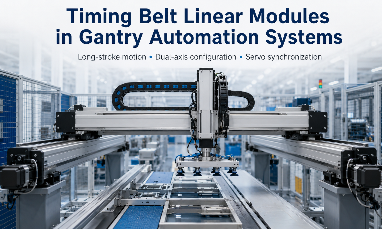
A timing belt gantry system is a multi-axis automation platform in which one or more axes are driven by toothed belts and pulleys. The timing belt transfers motor torque to the moving carriage, while linear guides support the payload and maintain the direction of motion.
A typical gantry configuration includes:
- Two parallel horizontal axes forming the main travel direction
- A crossbeam mounted between the parallel axes
- One transverse axis installed on the crossbeam
- An optional vertical axis for lifting and lowering
- Servo motors, couplings, sensors and motion controllers
- A gripper, vacuum tool, dispensing head or other end effector
Depending on the number and orientation of the axes, the system may be configured as an XY platform, an XZ cantilever, an XYZgantry robotor a synchronized dual-drive Cartesian system.
Why Timing Belt Linear Modules Are Used in Gantry Automation
Timingbelt linear modulesoffer several characteristics that make them suitable for gantry automation.
Long-Stroke Motion
Timing belt transmission is well suited to applications requiring long travel. Unlike a rotating ball screw, a timing belt does not experience screw-whipping problems as the stroke and rotational speed increase. This makes it practical for long production lines, large working envelopes and transfer systems.
The allowable stroke still depends on the module profile, belt tension, guide arrangement, installation method and required accuracy. Long modules must be supported correctly to prevent profile deflection and vibration.
High-Speed Reciprocating Movement
The moving components of a belt-driven module are relatively lightweight. Lower moving mass helps the axis accelerate and decelerate quickly, which can reduce transfer time between workstations.
This characteristic is valuable in applications such as sorting, packaging, palletizing and pick-and-place automation, where the gantry repeatedly moves between fixed positions.
Flexible Multi-Axis Integration
Timing belt modules can be combined into different Cartesian configurations. Their aluminum profiles provide convenient mounting surfaces for crossbeams, motors, sensors, cable carriers and auxiliary brackets.
Standardized interfaces also make it easier to expand a single-axis module into an XY, XZ or XYZ automation system.
Suitable Balance Between Speed and Repeatability
A properly designed timing belt gantry can provide stable repeat positioning for many industrial handling and processing tasks. Actual repeatability depends on belt stiffness, preload, pulley engagement, guide accuracy, structural rigidity, servo tuning and load conditions.
For applications requiring extremely high absolute positioning accuracy, engineers should also evaluate belt elongation, temperature variation and external measurement or compensation methods.
Common Gantry Structures
Single-Drive Gantry Structure
In a single-drive structure, one motor drives the main moving beam from one side or through a mechanical transmission connecting both sides. This configuration can reduce the number of motors and simplify control.
It is generally more suitable for relatively narrow gantries, moderate loads and structures with sufficient torsional rigidity. When the crossbeam is wide or heavily loaded, a single-side drive may create uneven forces and increase the risk of racking.
Dual-Drive Gantry Structure
A dual-drive gantry uses two parallel timing belt modules, with one drive system installed on each side of the crossbeam. The two axes move simultaneously and support the beam from both ends.
This configuration is commonly used when the gantry has:
- A wide working span
- A long primary travel distance
- A heavy crossbeam
- A centrally mounted transverse axis
- A large end-effector payload
- High acceleration or frequent direction changes
The main engineering challenge is maintaining synchronization between the two parallel axes.
XY Gantry System
An XY gantry provides motion in two horizontal directions. The parallel main axes move the crossbeam, while the transverse axis moves the tool across the beam.
XY systems are commonly used for dispensing, visual inspection, laser marking, surface processing and planar pick-and-place operations.
XYZ Gantry System
An XYZ gantry adds a vertical axis to the XY structure. The vertical axis allows the end effector to approach, lift or place the workpiece.
XYZ systems are widely used for loading and unloading, palletizing, assembly, packaging, warehouse transfer and machine tending.
Crossbeam Load and Structural Design
The crossbeam is one of the most important structural components in a gantry automation system. It carries the transverse axis, vertical axis, end effector, cables and sometimes additional equipment such as cameras or sensors.
The total moving load applied to the parallel timing belt modules may include:
- Crossbeam weight
- Transverse linear module weight
- Vertical-axis weight
- Motor and gearbox weight
- End-effector weight
- Workpiece payload
- Cable carrier and pneumatic hose weight
- Dynamic force generated during acceleration and deceleration
Engineers should not evaluate the payload using static weight alone. Acceleration creates additional inertial force, while an offset load creates pitching, yawing and rolling moments on the carriages and guides.
The approximate acceleration force can be expressed as:
F = m × a
whereFis the acceleration force,mis the moving mass andais the acceleration.
The selected timing belt modules must have sufficient load capacity, drive force and allowable moment capacity. A suitable safety factor should also be applied for unexpected impacts, load variation and long-term operation.
Crossbeam Deflection
A long crossbeam may bend under its own weight and the weight of the mounted axes. Excessive deflection can reduce positioning consistency, change tool height and increase vibration.
Crossbeam rigidity can be improved by:
- Increasing the beam section size
- Using a reinforced aluminum or steel structure
- Reducing the unsupported span
- Lowering the mass of the transverse and vertical axes
- Positioning heavy components closer to the support points
- Limiting acceleration when structural rigidity is insufficient
Servo Synchronization in Dual-Axis Gantries
When two timing belt modules drive the same crossbeam, their positions must remain synchronized. If one side moves farther than the other, the crossbeam can become skewed. This condition is commonly called gantry racking.
Racking can increase guide friction, create abnormal noise, overload the carriages and reduce positioning repeatability. Severe misalignment may damage the guides, belts or mounting structure.
Electronic Synchronization
In an electronically synchronized system, each parallel axis has its own servo motor and encoder. Themotion controllersends coordinated commands to both axes and monitors their position difference.
The controller may use master-slave control, gantry control or cross-coupled compensation to maintain alignment. The control strategy should include an allowable position-difference limit and a fault response if the two axes move out of synchronization.
Mechanical Synchronization
Mechanical synchronization connects both sides through a shaft, belt or gearbox arrangement. One motor drives the connected mechanism so that both sides move together.
This method can simplify electronic control, but the connecting components must be aligned carefully. Long connecting shafts may introduce torsional deformation, installation complexity and additional inertia.
Gantry Homing and Squaring
A dual-drive gantry normally requires a squaring procedure during homing. Each side may use an independent home sensor or reference position. The controller moves the axes until both sides establish their reference points and the crossbeam is aligned with the machine frame.
After homing, the controller maintains the defined positional relationship between the two axes. Home sensors, limit switches and mechanical stops should be installed so that the system can recover safely after power loss or maintenance.
Positioning Repeatability
Positioning repeatability describes the ability of the gantry to return to the same commanded position under the same operating conditions. It is an important parameter for pick-and-place, assembly, dispensing and inspection applications.
Factors that influence gantry repeatability include:
- Timing belt stiffness and preload
- Pulley manufacturing and installation accuracy
- Belt-to-pulley tooth engagement
- Linear guide accuracy
- Crossbeam rigidity
- Servo motor resolution and control tuning
- Load variation
- Acceleration and deceleration settings
- Temperature changes
- Gantry synchronization accuracy
Increasing belt tension does not always improve performance. Excessive tension can increase bearing load, friction and component wear. Belt tension should follow the module manufacturer’s recommended range.
Cable Management for Gantry Motion
A gantry system usually contains power cables, encoder cables, sensor wires, pneumatic hoses, vacuum tubing and communication lines. These components must move repeatedly without being stretched, twisted or trapped.
Cable carriers are commonly installed along the main, transverse and vertical axes. Their size and bending radius should match the cables and hoses inside them.
Good cable management should provide:
- Sufficient bending radius
- Separation between power and signal cables where necessary
- Proper strain relief at both ends
- Enough internal space without excessive filling
- No interference with the frame or moving carriage
- Suitable cable length for the full axis stroke
- Protection from oil, dust, chips or chemicals
The weight and drag force of the cable carrier should be included in the load calculation. On high-speed axes, an oversized or poorly supported cable carrier can create vibration and additional resistance.
End-Effector Integration
The end effector determines how the gantry interacts with the product or process. Common end effectors include:
- Pneumatic grippers
- Electric grippers
- Vacuum suction tools
- Dispensing valves
- Welding heads
- Inspection cameras
- Laser processing heads
- Screwdriving units
- Cutting or marking tools
When integrating an end effector, engineers should consider its weight, center of gravity, working force, air and electrical connections, mounting interface and required orientation.
An end effector mounted far from the carriage creates a larger moment load. This may require a wider carriage, dual guide blocks, a reinforced vertical axis or a different mounting arrangement.
The end-effector cycle should also be coordinated with axis motion. For example, a vacuum gripper may require confirmation of vacuum pressure before lifting, while a dispensing head may require a stable settling period before material is applied.
Typical Applications
Pick-and-Place Automation
A timing belt Cartesian robot can move products quickly between conveyors, trays and processing stations. Long travel and high acceleration help reduce non-processing time.
Machine Loading and Unloading
XYZ gantry systems can transfer parts into CNC machines, inspection equipment or assembly stations. The vertical axis handles lifting, while the horizontal axes position the workpiece.
Packaging and Sorting
Timing belt gantries can coordinate with conveyor systems to sort, group, stack or package products. Servo control allows the motion path to be adjusted for different product sizes and production recipes.
Dispensing and Gluing
XY or XYZ platforms can move dispensing heads along programmed paths. Stable motion, repeatable positioning and appropriate structural rigidity are important for maintaining bead consistency.
Visual Inspection
A camera mounted on a gantry can inspect large workpieces or multiple locations. The system can combine motion control with lighting, image acquisition and measurement software.
Palletizing and Warehouse Transfer
Long-stroke timing belt axes can cover multiple pallet or storage positions. A gripper or vacuum tool can handle cartons, trays, components and other lightweight or medium-weight products.
How to Select a Timing Belt Module for a Gantry System
Selection should be based on the complete gantry design rather than the nominal load of a single axis.
| Selection Factor | Engineering Consideration |
|---|---|
| Stroke | Required working area, overtravel, sensor position and maintenance space |
| Moving load | Crossbeam, other axes, end effector, cables and workpiece |
| Speed | Required transfer time and production cycle |
| Acceleration | Dynamic force, motor torque, belt load and structural vibration |
| Repeatability | Process tolerance, belt stiffness, guide accuracy and servo tuning |
| Moment load | Offset payload, end-effector extension and crossbeam arrangement |
| Drive configuration | Single drive, mechanical synchronization or dual servo drive |
| Environment | Dust, oil, moisture, cleanroom requirements and temperature |
| Installation orientation | Horizontal, vertical, side-mounted or inverted installation |
| Duty cycle | Operating hours, cycle frequency and expected service life |
Motor sizing should account for the total moving mass, acceleration force, friction, transmission efficiency and required safety margin. For vertical axes, the design must also consider gravity, holding brakes and protection against uncontrolled descent.
Installation and Commissioning Considerations
The mounting frame must be flat, rigid and properly aligned. Parallel modules should be installed using a consistent datum so that their guide rails remain parallel across the full stroke.
During commissioning, engineers should verify:
- Module mounting flatness and parallelism
- Crossbeam squareness
- Belt tension
- Pulley and coupling fastening
- Sensor and limit-switch operation
- Cable carrier movement
- Servo direction and feedback
- Dual-axis synchronization
- Emergency-stop behavior
- Positioning repeatability under actual load
Initial testing should begin at reduced speed and acceleration. Motion parameters can then be increased gradually while monitoring vibration, motor load, tracking error and mechanical noise.
Maintenance of Timing Belt Gantry Systems
Preventive maintenance helps maintain positioning stability and reduce unplanned downtime. Typical maintenance tasks include:
- Inspecting timing belts for wear, cracks and damaged teeth
- Checking belt tension and tracking
- Inspecting pulley and coupling fasteners
- Lubricating linear guides according to the maintenance schedule
- Checking cable carriers and flexible cables
- Cleaning dust and debris from the modules
- Verifying home sensors and limit switches
- Checking gantry squareness and synchronization
- Monitoring abnormal vibration, noise or motor current
Any change in repeatability, belt noise or crossbeam alignment should be investigated promptly. Continuing to operate a misaligned dual-axis gantry may accelerate wear across multiple components.
Conclusion
Timing belt linear modules provide a practical motion solution for gantry automation systems that require long travel, high speed and flexible multi-axis integration. They can be configured as XY platforms, XYZ Cartesian robots or synchronized dual-drive gantries for handling, packaging, inspection, dispensing and machine-tending applications.
Reliable operation depends on correct system-level engineering. The designer must evaluate the complete moving mass, crossbeam rigidity, moment loads, servo synchronization, positioning repeatability, cable management and end-effector requirements.
When the modules, frame, motors and control system are selected as an integrated solution, a timing belt gantry can deliver fast and repeatable motion across a large working area while remaining adaptable to different automation processes.
