 English

Atiming belt linear moduleis a high-speed linear motion system that converts the rotary motion of a motor into controlled straight-line movement. It combines a timing belt transmission, drive pulley, idler pulley, linear guide, carriage, tensioning mechanism, motor interface, sensors, andmotion controllerwithin a compact mechanical structure.
The basictiming belt linear module working principleis straightforward: a motor rotates the drive pulley, the drive pulley moves the toothed timing belt, and the belt pulls the carriage along a linear guide rail. By controlling motor rotation, speed, acceleration, and direction, the system can position the carriage at a specified location along the module stroke.
Unlike a conventional friction belt, a timing belt contains evenly spaced teeth that mesh with matching grooves on the timing pulleys. This positive engagement prevents normal operating slip between the belt and pulley, allowing motor rotation to be translated into repeatable linear displacement.
This article explains how atiming belt linear moduleworks, including rotary-to-linear motion conversion, timing pulley transmission, belt tension, guide rail support, servo control, position feedback, speed calculation, positioning accuracy, and the factors that influence motion performance.
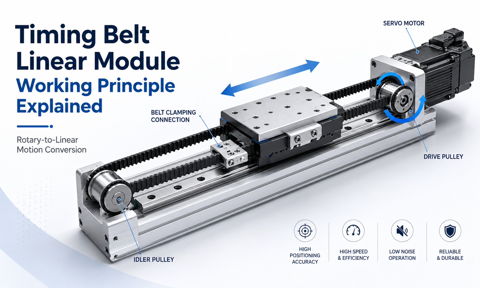
What Is the Working Principle of a Timing Belt Linear Module?
The working principle of a timing belt linear module is based on a closed-loop toothed belt running between a drive pulley and an idler pulley. The two ends of the moving belt section are mechanically connected to the carriage or belt clamping plate.
When the motor rotates the drive pulley, the pulley teeth engage with the timing belt teeth and move the belt around the pulley system. Because the carriage is connected to the belt, the carriage moves horizontally along the linear guide.
When the motor changes its direction of rotation, the belt also changes direction, causing the carriage to move in the opposite direction. The linear guide rail constrains the carriage so that it moves along one defined axis instead of rotating, tilting, or moving laterally.
The complete motion conversion can be summarized as follows:
- The motion controller sends a movement command.
- The servo drive or stepper drive supplies current to the motor.
- The motor shaft rotates according to the commanded direction and speed.
- The motor rotates the drive pulley through a direct coupling or transmission mechanism.
- The drive pulley teeth engage with the timing belt.
- The timing belt circulates between the drive pulley and idler pulley.
- The belt connection pulls or pushes the carriage along the module.
- The linear guide supports the carriage and maintains straight-line motion.
- Sensors or an encoder provide position and operating-status information.
- The control system stops the carriage at the programmed position.
Main Components Involved in Motion Transmission
The performance of a belt-driven linear system depends on the coordinated operation of several mechanical and control components. Each component has a specific role in converting motor rotation into stable linear movement.
Motor
The motor is the power source of the module. Timing beltlinear modulescan be driven by servo motors, stepper motors, or other rotary actuators, depending on the required speed, positioning accuracy, control method, and load.
A servo motor is commonly selected for applications requiring high acceleration, frequent start-stop motion, dynamic positioning, synchronized multi-axis control, and closed-loop feedback. A stepper motor may be suitable for lower-cost systems with moderate speed and relatively simple positioning requirements.
Drive Pulley
The drive pulley is connected to the motor shaft and transfers motor torque to the timing belt. Its teeth must match the pitch and tooth profile of the belt.
When the drive pulley completes one revolution, the belt moves by a distance determined by the pulley tooth count and the belt pitch. Therefore, the pulley diameter and tooth count directly influence linear displacement, speed, torque, and positioning resolution.
Idler Pulley
The idler pulley is installed at the opposite end of the module. It supports the timing belt, changes the direction of belt travel, and helps maintain a complete closed transmission loop.
Depending on the module design, the idler pulley may also be integrated with the belt tensioning mechanism. By adjusting its position, the installer can increase or decrease timing belt tension.
Timing Belt
The timing belt is the primary motion-transmission element. It normally contains a high-strength tensile core covered by wear-resistant belt material and molded teeth.
Common tensile materials include steel cord, fiberglass cord, and aramid fiber. The tensile core limits belt elongation under load, while the toothed surface maintains positive engagement with the pulley.
Compared with a flat belt or V-belt, a timing belt provides more predictable displacement because its teeth mesh mechanically with the pulley grooves.
Belt Clamp
The belt clamp mechanically connects the moving belt section to the carriage. As the belt travels, the clamp transfers belt force to the carriage.
The clamp must hold the belt securely without damaging the teeth or tensile cords. Poor clamping can create local belt deformation, position variation, noise, or eventual belt failure.
Carriage
The carriage is the moving platform used to support tools, grippers, sensors, workpieces, inspection cameras, dispensing heads, or other application equipment.
It transfers the external load to the guide blocks and receives driving force from the timing belt. The carriage structure must provide sufficient rigidity to resist vertical, lateral, and moment loads.
Linear Guide Rail
The linear guide rail supports and guides the carriage. The belt produces driving force, but the belt itself is not designed to carry all external loads or maintain precise travel geometry.
The guide rail absorbs radial load, lateral load, and overturning moments while maintaining a defined linear path. The quality of the guide rail and guide blocks strongly affects smoothness, straightness, stiffness, repeatability, and service life.
Belt Tensioning Mechanism
The tensioning mechanism establishes the correct initial tension in the timing belt. Proper tension keeps the belt teeth engaged with the pulleys, reduces belt vibration, and improves dynamic response.
Too little tension can cause tooth jumping, backlash-like movement, vibration, or delayed carriage response. Excessive tension increases bearing load, belt stress, friction, noise, and component wear.
Servo Drive and Motion Controller
The servo drive controls motor current, torque, speed, and position according to commands from the motion controller, programmable logic controller, industrial computer, or robot controller.
The controller defines the target position, velocity, acceleration, deceleration, movement sequence, and synchronization relationship with other axes.
Encoder and Position Sensors
An encoder measures motor shaft rotation, while limit switches, home sensors, or external linear encoders provide additional reference information.
These devices help the system establish its home position, prevent overtravel, detect faults, verify movement, and improve positioning reliability.
How Rotary Motion Is Converted into Linear Motion
Rotary-to-linear motion conversion occurs through the interaction between the drive pulley and the timing belt. The motor produces angular rotation, while the pulley converts that angular displacement into tangential belt movement.
Because the timing belt is connected to the carriage, tangential belt movement becomes linear carriage displacement.
For a timing pulley with a belt pitch ofpand a tooth count ofz, the theoretical belt movement per pulley revolution is:
Linear displacement per revolution = z × p
For example, if the pulley has 20 teeth and the belt pitch is 5 mm, one complete pulley revolution theoretically moves the belt:
20 × 5 mm = 100 mm
Therefore, one motor revolution produces approximately 100 mm of carriage travel when the pulley is directly connected to the motor and no additional gearbox ratio is used.
If the motor rotates at 1,500 revolutions per minute, the theoretical linear speed is:
Linear speed = 100 mm × 1,500 ÷ 60 = 2,500 mm/s
This relationship explains why timing belt modules can achieve high linear speeds. A relatively small pulley can produce a significant travel distance during every motor revolution.
How the Drive Pulley Transmits Motor Torque
The drive pulley converts motor torque into tangential pulling force on the belt. The motor may be connected to the pulley through a coupling, gearbox, shaft, or integrated motor mount.
When torque is applied to the drive pulley, the pulley teeth push against the matching belt teeth. The belt then develops tension on the driving side and transfers force to the carriage connection.
The available linear driving force depends on several factors:
- Motor output torque
- Drive pulley pitch radius
- Gearbox ratio, when used
- Timing belt tensile capacity
- Belt tooth engagement
- Initial belt tension
- Acceleration requirement
- Carriage and payload mass
- Guide rail friction
- External process resistance
For the same motor torque, a smaller pulley generally produces greater linear force but lower travel per revolution. A larger pulley produces higher linear travel per revolution but reduces the available tangential force.
Pulley selection therefore requires a balance between speed, force, motor resolution, belt life, and minimum bending radius.
Role of the Idler Pulley
The idler pulley does not normally receive direct motor power, but it is essential to the operation of the transmission system.
Its functions include:
- Supporting the timing belt at the opposite end of the module
- Maintaining the closed belt path
- Changing belt travel direction
- Maintaining alignment between the belt and pulley system
- Providing an adjustment point for belt tension
- Reducing unsupported belt movement
The idler pulley must rotate smoothly with low bearing resistance. Poor bearing condition, pulley misalignment, or contamination can increase noise and motion resistance.
If the idler pulley is not parallel to the drive pulley, the belt may track toward one side, contact pulley flanges, wear unevenly, or generate unstable motion.
Why Timing Belt Tension Is Important
Timing belt tension is one of the most important factors affecting thebelt driven linear actuator principle. The belt must be tensioned sufficiently to remain engaged with the pulley during acceleration, deceleration, and load reversal.
Effects of Insufficient Belt Tension
If belt tension is too low, the system may experience:
- Delayed carriage response after motor reversal
- Reduced positioning repeatability
- Belt vibration during high-speed motion
- Tooth jumping under high acceleration
- Impact noise during direction changes
- Uneven motion at low speed
- Position deviation under changing loads
Although a timing belt does not normally slip like a friction belt, insufficient tension may allow the teeth to disengage momentarily from the pulley grooves under excessive dynamic load.
Effects of Excessive Belt Tension
Excessive belt tension can also damage system performance. Possible consequences include:
- Increased motor load
- Higher pulley bearing stress
- Accelerated belt fatigue
- Increased friction and temperature
- Greater noise
- Reduced bearing service life
- Deformation of shafts or end blocks
The correct tension should follow the module manufacturer's specifications. Belt tension should not be adjusted only by subjective feel, especially in high-speed or precision applications.
How the Linear Guide Controls the Motion Path
The timing belt creates motion, while the linear guide controls the path of motion. These two functions should not be confused.
Without a guide rail, the belt could pull the carriage forward, but it could not reliably prevent vertical displacement, lateral movement, yaw, pitch, or roll.
The linear guide system normally consists of one or more guide rails and recirculating-ball guide blocks. The guide blocks are attached to the carriage and move along the rail with low friction.
The guide system performs several functions:
- Supports the carriage and payload
- Maintains linear travel accuracy
- Resists vertical and lateral forces
- Resists pitch, yaw, and roll moments
- Reduces motion friction
- Prevents the timing belt from carrying structural loads
- Maintains stable movement during acceleration
For long carriages or high moment loads, manufacturers may use two guide rails, multiple guide blocks, a wider rail arrangement, or a reinforced base profile.
Servo Control in a Timing Belt Linear Module
A servo-driven timing belt module combines mechanical transmission with electronic closed-loop control. The servo motor contains an encoder that continuously measures shaft position or rotational speed.
The motion controller sends a target command to the servo drive. The servo drive compares the commanded motion with encoder feedback and adjusts motor current to reduce the difference.
This process can occur many times per second, allowing the system to respond quickly to changes in load, speed, and position.
A typical servo-controlled movement includes the following stages:
- Receiving the target position from the controller
- Calculating the required motion profile
- Accelerating the motor and carriage
- Maintaining the programmed travel speed
- Decelerating before the target position
- Stopping at the commanded location
- Holding the position against external disturbance
- Reporting completion or fault status to the controller
The servo system can control position, speed, or torque, depending on the machine design.
Position Control Mode
In position mode, the controller commands a defined amount of travel. This mode is widely used for pick-and-place systems, packaging equipment, electronic assembly, inspection systems, and material transfer.
Speed Control Mode
In speed mode, the controller regulates the travel velocity rather than stopping at many programmed positions. It may be used for scanning, coating, continuous inspection, or synchronized conveyor applications.
Torque Control Mode
Torque mode controls the motor's output torque. It may be used in specialized applications where force limitation or tension control is required, although timing belt modules are primarily selected for positioning and high-speed transfer.
How Position Feedback Works
Position feedback allows the control system to determine whether the commanded movement has been completed correctly.
Most servo-driven modules use a rotary encoder installed on the motor. The controller calculates carriage position from motor rotation, pulley tooth count, belt pitch, and transmission ratio.
This is known as semi-closed-loop control because the encoder measures motor rotation rather than directly measuring the carriage position.
For applications requiring higher absolute positioning accuracy, an external linear encoder can be installed along the module. The linear encoder measures the actual carriage location and can detect errors caused by belt elasticity, structural deformation, thermal expansion, or transmission variation.
Position feedback devices may include:
- Motor rotary encoder
- Linear encoder
- Magnetic scale
- Optical scale
- Home sensor
- Positive limit switch
- Negative limit switch
- External machine vision feedback
Open-Loop and Closed-Loop Operation
Timing belt linear modules can operate in open-loop or closed-loop control systems.
Open-Loop Control
An open-loop system sends movement pulses to a stepper motor without continuously verifying the actual final position. The controller assumes that the motor has followed every command.
This approach is simple and cost-effective, but overload, excessive acceleration, obstruction, or motor stall can cause lost steps and position error.
Closed-Loop Control
A closed-loop servo system continuously compares commanded movement with encoder feedback. If the actual motion differs from the command, the drive increases or reduces motor output to correct the error.
Closed-loop control provides better dynamic response, higher operating speed, greater acceleration capability, motor alarm functions, and more reliable position monitoring.
Motion Profile: Acceleration, Constant Speed and Deceleration
A timing belt module does not normally move from zero speed to maximum speed instantaneously. The controller generates a motion profile that determines how the axis accelerates, travels, and stops.
A typical movement contains three main stages:
Acceleration Stage
The motor increases speed from zero to the programmed travel speed. During this stage, the belt must transmit enough force to accelerate the carriage, payload, and connected equipment.
High acceleration increases productivity but also increases belt tension variation, structural vibration, motor torque demand, and guide load.
Constant-Speed Stage
The carriage moves at the programmed maximum speed. Long-stroke modules may spend a significant portion of the cycle in this stage.
Stable belt tracking, pulley balance, base rigidity, and guide alignment are particularly important during high-speed travel.
Deceleration Stage
The motor reduces speed before the target position. The timing belt transmits force in the opposite direction to decelerate the moving mass.
Poorly configured deceleration can produce vibration, overshoot, carriage oscillation, or excessive settling time.
Many servo systems use trapezoidal or S-curve motion profiles. An S-curve profile reduces sudden changes in acceleration and can improve smoothness when moving delicate products or heavy payloads.
How Direction Reversal Occurs
To reverse carriage direction, the controller reverses motor rotation. The drive pulley then moves the belt in the opposite direction.
During direction reversal, the load on the two sides of the belt changes rapidly. One side becomes the tension side while the other side becomes the return side.
This transition makes belt tension, carriage rigidity, servo tuning, and mechanical clearance especially important. Inadequate tension or an overly flexible structure can create a small delay between motor reversal and carriage response.
For applications involving frequent reciprocating movement, the module should be selected according to dynamic load rather than only static payload capacity.
Factors Affecting Positioning Accuracy
A timing belt module can provide reliable repeatable positioning, but its absolute accuracy is affected by both mechanical and control factors.
Important factors include:
- Timing belt tensile stiffness
- Belt length and operating stroke
- Initial belt tension
- Payload mass
- Acceleration and deceleration
- Pulley manufacturing accuracy
- Pulley eccentricity
- Belt tooth pitch variation
- Guide rail accuracy
- Base profile straightness
- Motor encoder resolution
- Servo tuning quality
- Temperature variation
- External process force
- Installation alignment
Belt Elasticity
A timing belt is more elastic than a ball screw. Under load, it can elongate slightly. The amount of elongation depends on belt construction, tensile cord material, belt width, belt length, and transmitted force.
This is why very long timing belt modules may provide excellent speed and repeatability but lower absolute positioning accuracy than short-strokeball screw modules.
Pulley Accuracy
Pulley tooth geometry, pitch diameter accuracy, concentricity, and shaft installation influence the relationship between motor rotation and belt movement.
Pulley eccentricity can create periodic position variation, speed fluctuation, or vibration during each revolution.
Guide Rail Accuracy
The guide rail determines carriage straightness and mechanical stability. Poor rail alignment can increase resistance, create uneven movement, or place additional load on the motor.
Servo Resolution
The motor encoder and control system determine how precisely motor rotation can be commanded and measured. However, high encoder resolution alone does not guarantee high carriage accuracy because belt elasticity and mechanical errors must also be considered.
Repeatability and Absolute Positioning Accuracy
Repeatability and positioning accuracy are related but different specifications.
Repeatabilitydescribes how closely the carriage returns to the same position after repeated movements under similar conditions.
Absolute positioning accuracydescribes how closely the actual carriage position matches the programmed coordinate across the complete stroke.
A timing belt linear module may achieve good repeatability even when its absolute position contains a small systematic error. Calibration or controller compensation can reduce repeatable systematic errors, but it cannot completely eliminate variable belt deformation caused by changing loads.
How Home and Limit Sensors Work
Home and limit sensors are important parts of the operating sequence.
Home Sensor
When the machine starts, the controller may not know the carriage's absolute position. The carriage moves toward the home sensor at a controlled speed until the sensor is activated.
The controller then establishes a reference coordinate. Some systems use an encoder index signal together with the home sensor to improve homing repeatability.
Positive and Negative Limit Sensors
Limit sensors are installed near both ends of the usable stroke. They prevent the carriage from moving beyond the permitted travel range.
If a limit sensor is triggered unexpectedly, the controller normally stops movement and generates an alarm.
Mechanical End Stops
Mechanical end stops provide a final protective measure if electrical limit control fails. They are not intended to be used as normal stopping positions because repeated impact can damage the carriage, belt, guide blocks, or end structure.
Timing Belt Linear Module Speed Calculation
The theoretical linear speed can be calculated using pulley tooth count, belt pitch, and motor speed:
Linear speed = Pulley tooth count × Belt pitch × Motor speed ÷ 60
Where:
- Linear speed is measured in millimeters per second
- Pulley tooth count is the number of teeth on the drive pulley
- Belt pitch is measured in millimeters
- Motor speed is measured in revolutions per minute
If a gearbox is installed, the gearbox ratio must also be included in the calculation.
The actual usable speed may be lower than the theoretical value because of motor torque limits, belt vibration, guide capacity, stroke length, payload, acceleration distance, and structural rigidity.
Timing Belt Linear Module Force Transmission
The linear force generated by the module is related to motor torque and pulley pitch radius:
Linear force ≈ Motor torque ÷ Pulley pitch radius
This simplified relationship does not include efficiency loss, acceleration force, guide friction, belt pretension, or safety factors, but it illustrates an important design principle.
A smaller pulley radius increases linear force for the same motor torque, while a larger pulley radius increases linear travel per revolution.
The required driving force should include:
- Force needed to accelerate the moving mass
- Guide rail friction
- External processing resistance
- Cable carrier resistance
- Inclined or vertical load effects
- Safety margin
Timing belt modules are commonly used for horizontal motion. Vertical installations require additional consideration of gravity, brake systems, counterbalance mechanisms, load drop protection, and motor holding torque.
Servo Tuning and Dynamic Performance
Servo tuning determines how quickly and accurately the motor responds to motion commands.
If servo gains are too low, the system may respond slowly, produce excessive following error, or require a long settling time. If gains are too high, the axis may vibrate, generate noise, oscillate at the target position, or trigger an alarm.
Servo tuning must consider:
- Payload mass
- Carriage inertia
- Pulley inertia
- Belt elasticity
- Module stroke
- Base rigidity
- Installation structure
- Acceleration profile
- External process force
Because a timing belt has some elasticity, an overly aggressive servo setting may excite belt vibration. Proper acceleration limits, filtering, feedforward control, and S-curve profiles can improve motion stability.
Timing Belt Tooth Engagement and Slip Prevention
A toothed timing belt transmits motion through positive mechanical engagement rather than friction alone. Under normal working conditions, the belt teeth remain aligned with the pulley grooves.
However, tooth skipping may occur when:
- Belt tension is insufficient
- The commanded acceleration is too high
- The payload exceeds the design capacity
- The pulley has too few engaged teeth
- The belt or pulley teeth are worn
- A foreign object enters the pulley area
- The carriage collides with an obstacle
- The axis reaches a mechanical end stop
Tooth skipping changes the relationship between motor position and carriage position. A motor encoder may not detect this mechanical displacement because the motor itself may continue to rotate as commanded.
Correct belt selection, sufficient tooth engagement, proper tension, and appropriate acceleration settings are therefore essential.
Why Timing Belt Modules Are Suitable for Long-Stroke Motion
Timing belt modules are particularly suitable for long-stroke applications because the transmission element is lightweight and does not rotate as a long rigid shaft.
A long ball screw may be limited by screw whip, critical rotational speed, inertia, and support requirements. A timing belt can circulate over a long distance without the same type of rotating-shaft limitation.
This makes thelinear belt drive systemsuitable for:
- Long material-transfer axes
- Packaging machinery
- Warehouse automation
- Gantry systems
- Pick-and-place equipment
- Electronic assembly lines
- Vision inspection systems
- Laser processing equipment
- Multi-station production lines
For extremely long strokes, belt vibration, base straightness, installation support, thermal expansion, and cable management must still be considered.
Timing Belt Module Versus Ball Screw Module Working Principle
A timing belt module and a ball screw module both convert motor rotation into linear movement, but they use different transmission mechanisms.
| Comparison Item | Timing Belt Linear Module | Ball Screw Linear Module |
|---|---|---|
| Transmission element | Toothed timing belt and pulleys | Ball screw and recirculating nut |
| Motion conversion | Pulley rotation creates belt travel | Screw rotation creates nut travel |
| Typical advantage | High speed and long stroke | High rigidity and positioning accuracy |
| Transmission elasticity | Relatively higher | Relatively lower |
| Critical-speed limitation | No long rotating screw | Long screw speed may be limited |
| Maintenance focus | Belt tension and tooth condition | Lubrication and screw condition |
A timing belt module is usually preferred when speed, stroke length, and cycle time are the main priorities. A ball screw module is often preferred when high thrust, rigidity, and precision are more important.
Example of a Complete Operating Cycle
Consider a timing belt module used to move an inspection camera between several positions on an electronics production line.
- The machine powers on and checks safety signals.
- The carriage moves slowly toward the home sensor.
- The home sensor establishes the zero reference.
- The controller sends the first target position to the servo drive.
- The servo motor accelerates the drive pulley.
- The timing belt pulls the carriage along the guide rail.
- The motor encoder reports rotational position to the servo drive.
- The carriage decelerates as it approaches the inspection point.
- The carriage stops and the camera captures an image.
- The controller receives the inspection-complete signal.
- The module moves to the next programmed position.
- After all inspections are complete, the carriage returns to the standby position.
During this cycle, the timing belt provides high-speed transmission, the guide rail maintains carriage stability, and the servo system controls acceleration, speed, and stopping position.
Common Factors That Disturb Smooth Motion
Even when the basic timing belt actuator working principle is correct, improper installation or component condition can disturb movement.
Common causes include:
- Incorrect belt tension
- Drive and idler pulley misalignment
- Guide rail installation error
- Loose motor coupling
- Loose belt clamp
- Worn pulley bearings
- Contaminated guide rail
- Insufficient guide lubrication
- Excessive payload
- Excessive acceleration
- Poor servo tuning
- Weak mounting structure
- Uneven base support
- Improper cable carrier installation
Inspection should distinguish between transmission problems, guide-system problems, motor-control problems, and external installation problems.
Design Considerations for Reliable Operation
To ensure reliable operation, the timing belt linear module should be selected and configured according to actual application conditions.
Important design parameters include:
- Required effective stroke
- Maximum travel speed
- Required acceleration
- Payload mass
- Load center position
- Radial, axial, and moment loads
- Positioning repeatability
- Required absolute accuracy
- Operating orientation
- Cycle frequency
- Duty cycle
- Environmental dust and contamination
- Operating temperature
- Motor power and brake requirement
- Sensor configuration
- Controller communication method
Selection based only on payload weight is insufficient. A lightweight load mounted far from the carriage surface can generate a large overturning moment, while a high acceleration may require much greater belt force than a low-speed static calculation suggests.
Advantages of the Timing Belt Transmission Principle
The timing belt transmission principle provides several practical advantages:
- High linear travel speed
- Long available stroke
- High acceleration capability
- Relatively low moving mass
- Low transmission noise
- Simple mechanical structure
- No long rotating screw
- Good repeatability for transfer applications
- Flexible motor mounting configurations
- Suitable for multi-axis automation systems
These characteristics make timing belt modules especially effective for applications where products, tools, or sensors must be moved rapidly across medium or long distances.
Limitations of the Timing Belt Transmission Principle
The same structure also has limitations that must be considered:
- Lower transmission stiffness than a ball screw
- Belt elongation under changing loads
- Lower suitability for very high thrust
- Position variation over extremely long strokes
- Need for correct belt tension
- Potential tooth wear after long service
- Greater sensitivity to aggressive servo tuning
- Possible vibration in long unsupported belt sections
A timing belt module should not automatically be selected only because it can provide high speed. The required accuracy, thrust, load moment, operating orientation, and service environment must also be evaluated.
Frequently Asked Questions
How does a timing belt linear module work?
A motor rotates a toothed drive pulley. The pulley moves a matching timing belt, and the timing belt moves a carriage connected to it. A linear guide supports the carriage and restricts movement to one straight axis.
Does a timing belt linear module use friction to transmit motion?
The system uses positive engagement between the belt teeth and pulley grooves. Friction contributes to overall contact behavior, but the primary transmission mechanism is mechanical tooth engagement.
Can a timing belt module provide precise positioning?
Yes. It can provide reliable repeatable positioning when properly selected, tensioned, installed, and controlled. However, belt elasticity normally makes it less suitable than a ball screw module for applications demanding extremely high absolute accuracy and rigidity.
What determines the travel distance per motor revolution?
The travel distance is determined mainly by the timing pulley tooth count and belt pitch. With direct drive, the theoretical movement per pulley revolution equals pulley tooth count multiplied by belt pitch.
Why is belt tension necessary?
Correct belt tension maintains tooth engagement, improves directional response, controls vibration, and reduces the risk of tooth skipping. Both insufficient and excessive tension can reduce performance and component life.
What is the function of the linear guide?
The linear guide supports the payload, controls the direction of motion, resists external forces and moments, and maintains carriage stability. The belt provides driving force but should not serve as the main load-supporting element.
Can the module be used vertically?
Yes, but vertical operation requires careful calculation of gravity load, motor torque, braking, holding force, load-drop prevention, and safety factors. A motor brake or counterbalance system may be necessary.
Why does a timing belt module suit long strokes?
The belt is lightweight and does not require a long screw shaft to rotate at high speed. This avoids many critical-speed and screw-whip limitations associated with long ball screws.
Can an external linear encoder improve accuracy?
Yes. An external linear encoder measures actual carriage position and can compensate for some errors that a motor-mounted rotary encoder cannot directly detect.
What causes tooth skipping?
Common causes include insufficient belt tension, excessive acceleration, overload, inadequate tooth engagement, worn teeth, mechanical collision, or foreign material entering the pulley area.
Conclusion
Thetiming belt linear module working principleis based on converting motor rotation into linear belt travel through a toothed drive pulley. The moving timing belt transfers force to the carriage, while the linear guide supports the load and maintains a controlled straight-line path.
The drive pulley determines belt movement, the idler pulley completes the transmission loop, the tensioning mechanism maintains tooth engagement, and the servo system controls speed, acceleration, direction, and stopping position. Encoders and sensors provide the feedback and reference signals required for reliable automated operation.
Because this transmission structure supports high speed, high acceleration, long strokes, and relatively low moving mass, timing belt linear modules are widely used in packaging, material handling, electronics assembly, visual inspection, laser processing, logistics automation, gantry systems, and multi-axis machinery.
Reliable performance depends on more than the belt alone. Correct pulley selection, proper belt tension, guide rail capacity, structural rigidity, motor sizing, servo tuning, sensor configuration, installation alignment, and application load analysis must all be considered as part of the complete linear motion system.
